Hello all,
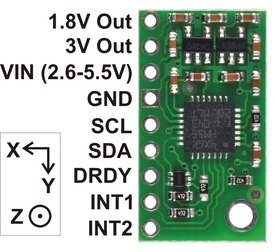
This is my first post… usually I just search the forums, but I haven’t had any luck with searching for someone with this issue. In summary, I recently ported a project I’m working on from an Arduino with a LSM303DLM daughter board to a custom PCB running an ATMEGA644PA and an LSM303DLHC. The problem I am having is the final heading result is now off by 90 degrees (when the x-axis is pointing north, the heading is telling me I’m facing east).
Has anybody seen anything similar to this issue?
A couple of notes:
- I am aware of the new accelerometer address, and can successfully communicate with it via I2C.
- I have the high resolution bit enabled (but I have also tried it without this enabled).
- I downloaded the LSM303DLHC arduino library, and took note of the differences in the code vs. the LSM303DLM library. I believe I’ve updated my code accordingly.
- To the best of my knowledge, I’ve calibrated the compass correctly (the same as I did with the LSM303DLM, which worked fine).
Here are the relevant snippets of code:
static void smrt_io_compass_init()
{
	TWSR = 0;  // clear bit-rate prescale bits
	TWBR = 17; // produces an SCL frequency of 400 kHz with a 20 MHz CPU clock speed

	//enable accelerometer
	i2c_start();
	i2c_write_byte(ACC_ADDRESS); // write acc
	i2c_write_byte(0x20); // CTRL_REG1_A
	i2c_write_byte(0x77); // normal power mode, 400 Hz data rate, all axes enabled

	i2c_start();
	i2c_write_byte(ACC_ADDRESS);
	i2c_write_byte(0x23); // CTRL_REG4_A
	i2c_write_byte(0x8);  // enable high resolution mode
	i2c_stop();

	//enable magnetometer
	i2c_start();
	i2c_write_byte(MAG_ADDRESS); // write mag
	i2c_write_byte(0x02); // MR_REG_M
	i2c_write_byte(0x00); // continuous conversion mode
	i2c_stop();
}

void smrt_io_read_data(vector *a, vector *m)
{
	smrt_io_read_data_raw(a, m);

	// shift and scale
	m->x = (m->x - m_min.x) / (m_max.x - m_min.x) * 2 - 1.0;
	m->y = (m->y - m_min.y) / (m_max.y - m_min.y) * 2 - 1.0;
	m->z = (m->z - m_min.z) / (m_max.z - m_min.z) * 2 - 1.0;
}

static void smrt_io_read_data_raw(vector *a, vector *m)
{
	// read accelerometer values
	i2c_start();
	i2c_write_byte(ACC_ADDRESS); // write acc
	i2c_write_byte(0xa8); // OUT_X_L_A, MSB set to enable auto-increment
	i2c_start();		  // repeated start
	i2c_write_byte(ACC_ADDRESS+1); // read acc
	unsigned char axl = i2c_read_byte();
	unsigned char axh = i2c_read_byte();
	unsigned char ayl = i2c_read_byte();
	unsigned char ayh = i2c_read_byte();
	unsigned char azl = i2c_read_byte();
	unsigned char azh = i2c_read_last_byte();
	i2c_stop();

	// read magnetometer values
	i2c_start();
	i2c_write_byte(MAG_ADDRESS); // write mag
	i2c_write_byte(0x03); // OUTXH_M
	i2c_start();		  // repeated start
	i2c_write_byte(MAG_ADDRESS + 1); // read mag
	unsigned char mxh = i2c_read_byte();
	unsigned char mxl = i2c_read_byte();
	// for the DLM and DLHC, the register address for Z comes before Y
	unsigned char mzh = i2c_read_byte();
	unsigned char mzl = i2c_read_byte();
	unsigned char myh = i2c_read_byte();
	unsigned char myl = i2c_read_last_byte();
	i2c_stop();

  // combine high and low bytes, then shift right to discard lowest 4 bits (which are meaningless)
  // GCC performs an arithmetic right shift for signed negative numbers, but this code will not work
  // if you port it to a compiler that does a logical right shift instead.
  a->x = ((int16_t)(axh << 8 | axl)) >> 4;
  a->y = ((int16_t)(ayh << 8 | ayl)) >> 4;
  a->z = ((int16_t)(azh << 8 | azl)) >> 4;

	m->x = mxh << 8 | mxl;
	m->y = myh << 8 | myl;
	m->z = mzh << 8 | mzl;
}

// Returns a heading (in degrees) given an acceleration vector a due to gravity, a magnetic vector m, and a facing vector p.
int smrt_io_get_heading(const vector *a, const vector *m, const vector *p)
{
	vector E;
	vector N;

	vector_normalize(a);

	// cross magnetic vector (magnetic north + inclination) with "down" (acceleration vector) to produce "east"
	vector_cross(m, a, &E);
	vector_normalize(&E);

	// cross "down" with "east" to produce "north" (parallel to the ground)
	vector_cross(a, &E, &N);

	// compute heading
	int heading = round(atan2(vector_dot(&E, p), vector_dot(&N, p)) * 180 / M_PI);
	if (heading < 0)
	heading += 360;
	return heading;
}
