Hi guys, I ordered a 6 channel maestro rc controller and the medium mosfet and i soldered everything in place and connected everything the way it’s supposed to be according to the diagram but I’m getting no lights via the mosfet.
What I’m trying to do… I have the maestro programmed to hit a button, it turns 2 servos, then some leds flicker 2 times and turn on. hit the button again it turns the servos and the lights turn off.
Because the led lights are being run off of the signal cable they’re not that bright. I wanted to make them brighter but have the same flicker effect.
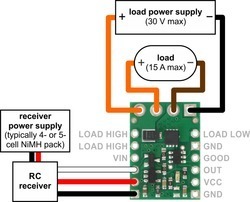
I have not changed anything on the maestro, I just ran the servo cable directly to the mosfet (as shown in the diagram. Connected my 12v power source to the outsides (+ and -) and the leds I want to power to the 2 leads on the inner part (+ and -) as shown in the diagram. Its not working.
I’ve tried setting the channel 3 (the led one) as a servo using the maestro control panel, instead of output. I’ve ran the slider back and forth while everything is connected and the lights do not come on.
I do have 1 question about the diagram. from the load power its connected to a ground with a black line, the “load” is connected via a brown wire, why is that?
I’ve connected the “load” negative lead to the GND terminal just below “load low” and the lights turn on.
The mosfet blinks yellow 1 time every second.
I’m out of ideas, any help would be more then greatly appreciated.