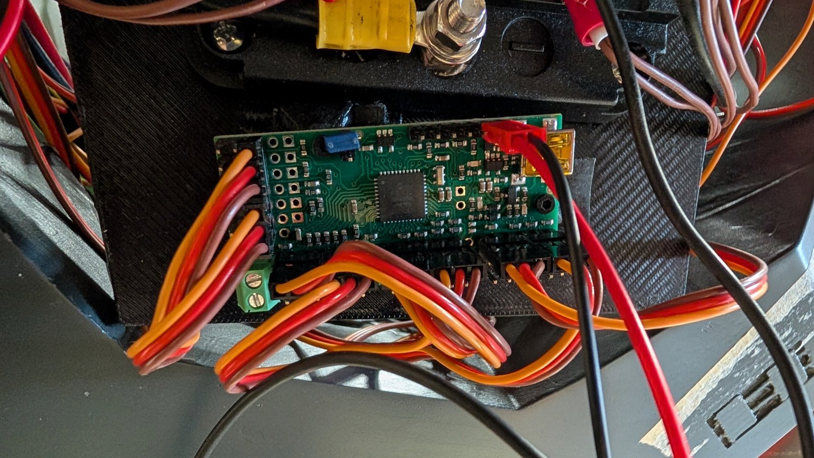
I have a quick question about power supply. I have a Maestro24 here. I’ve only connected the signal wire to the pins. The servos get their power separately. If I understand correctly, the Maestro can handle between 5 and 16V. Since it’s only supposed to run the program, is 5V sufficient? Or should I still use 12V? And should I use the connector or can I use the screw terminals? If so, I’ll probably need to use the jumper.
Hello.
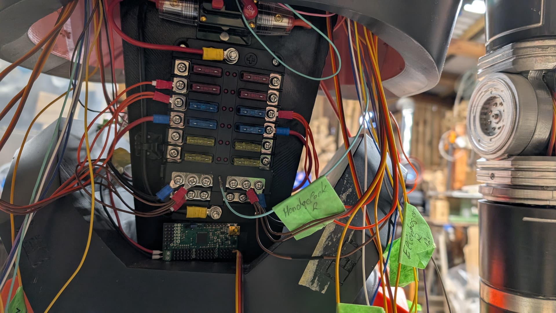
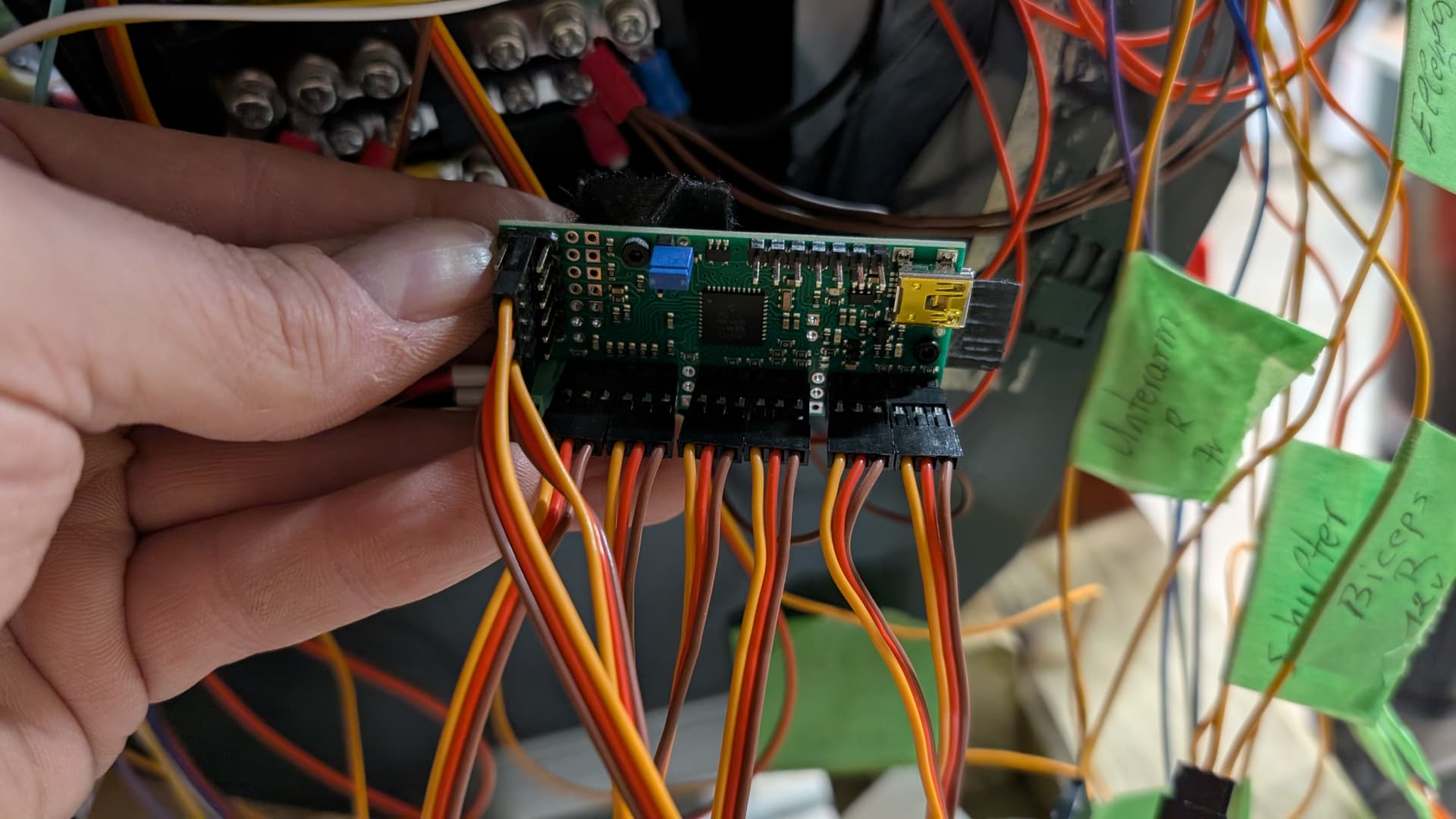
It is hard to tell what connections you are making from your pictures, but it looks like you might be connecting your servo cables in the wrong orientation so they are across the signal channels on the Maestro instead of properly aligning with the GND, power, and signal outputs. Additionally, your connections on the short side of the Maestro board (i.e. channels 18-24) are similarly all being made to the servo power rail. To properly power the servos separately, you should only be making the signal and ground connection to the Maestro.
As far as powering the Maestro, 5V would probably be fine as long as it is stable, but if there is noise on the line, it could cause the Maestro to brownout and reset. So, if you have 12V available already, that would probably be a better option. If you are powering the servos separately from the Maestro board, you can just power the Maestro through its VIN pin directly (i.e. you should not use the terminal blocks or jumper).
Brandon
Thank you very much, then I’ll go with the 12V. And just to clarify:
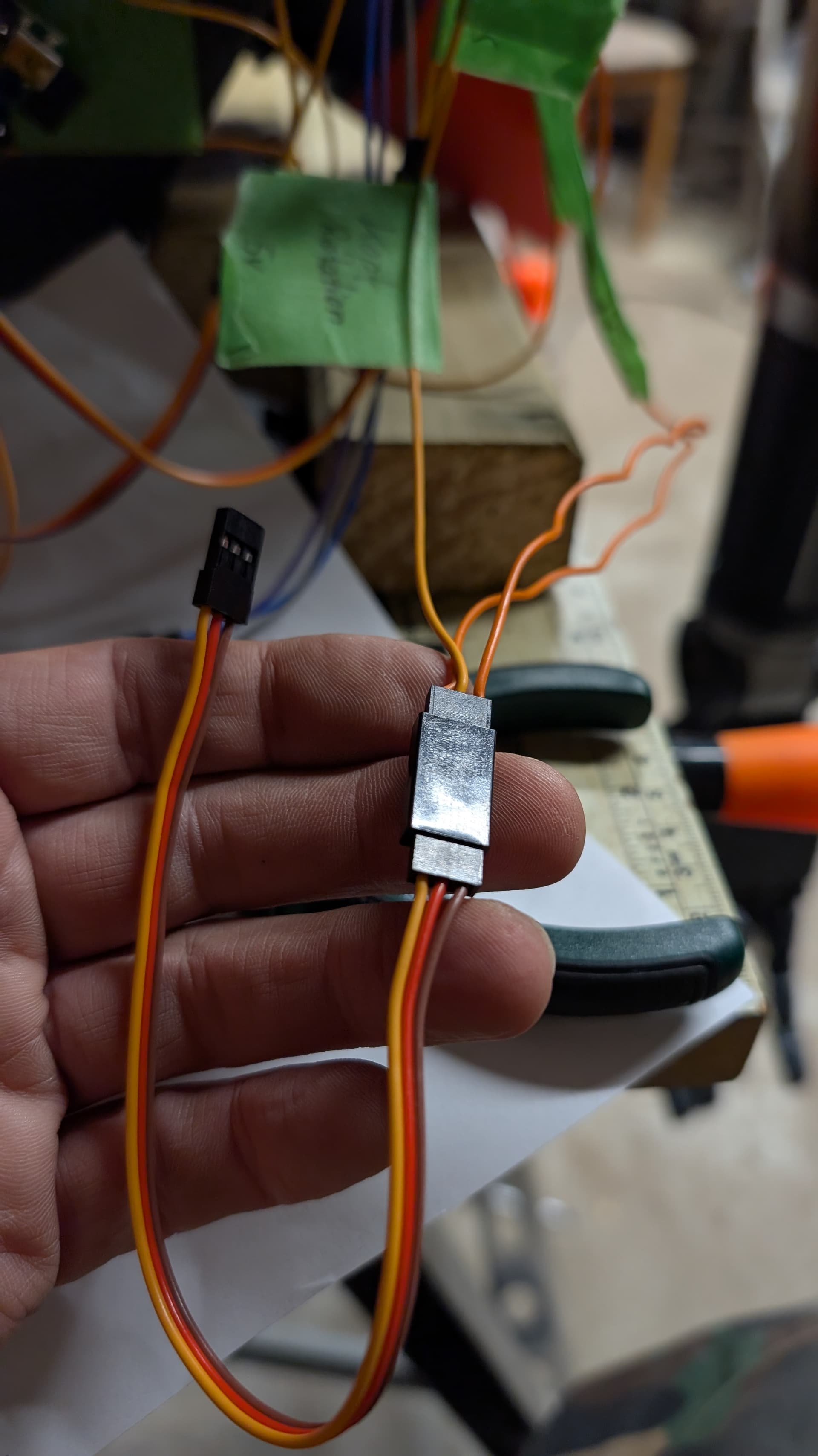
Yes, it’s not entirely clear in the pictures. I’ve separated the servo leads. Positive and negative are separate, and the signal leads go to the Maestro. I’ve only used extension cables here to make them easier to connect.
That’s much clearer! Thank you.
Just to make sure you saw my other comments, you should still have a common ground between the Maestro and each servo, and it looks like your connections to channels 18 through 24 are connected to the servo power rail instead of the signal pins.
Brandon