
I have a 4-channel multiplexer to switch from RC control to Jetson Nano, autonomous control. For some reason, I am unable to get SEL to recognize a valid signal. I have read the manual, including Section 6.2, I am using default 1.696ms pulse width at 50Hz pulse rate with no luck blinking led on either master or slave. I am embarrassed to report that have worked on this for a couple of weeks. A simple python hello world is what I need. I am using a Jetson Nano with i2c to pca9685, then to the multiplexer, the multiplexer out will control jetracer, made using FMS Chevrolet K5 Blazer rock crawler. Thankyou, mike
Hello, Mike.
I moved your post to its own thread since it was different enough from the original thread (and that thread was 13 years old!).
Could you post some pictures of your setup that show all of your connections along with a short video showing your setup and the behavior of the yellow indicator LED on the multiplexer when it runs? For reference, the four LED states are described in the “Outputs and Indicator LED” section of our RC Switch user’s guide.
Also, you mentioned not being able to blink an LED on either the master or slave outputs; could you describe in more detail how you’re trying to test the board?
Brandon
My code, I tried varies values for pulse width and pulse rate with no luck:
import time
import board
import busio
import adafruit_pca9685

# Create I2C bus
i2c = busio.I2C(board.SCL, board.SDA)

# Create PCA9685 object
pca = adafruit_pca9685.PCA9685(i2c)
pca.frequency = 50 # Set PWM frequency to 50 Hz

# Calculate correct duty cycle
def calculate_duty_cycle(pulse_width, period):
return min(int((pulse_width / period) * 4096), 4095)

# Set valid master signal for SEL pin on multiplexer
def set_master_signal():
pulse_width = 1.0 # Master signal pulse width < 1.6 ms
period = 1 / 50.0 # Period in seconds (50 Hz frequency = 20 ms period)
duty_cycle = calculate_duty_cycle(pulse_width, period)
pca.channels[1].duty_cycle = duty_cycle
print("Master")

# Set valid slave signal for SEL pin on multiplexer
def set_slave_signal():
pulse_width = 2.0 # Slave signal pulse width > 1.6 ms
period = 1 / 50.0 # Period in seconds (50 Hz frequency = 20 ms period)
duty_cycle = calculate_duty_cycle(pulse_width, period)
pca.channels[2].duty_cycle = duty_cycle
print("Slave")

# Blink LED on a given channel
def blink_led(channel):
for _ in range(5): # Blink LED 5 times
pca.channels[channel].duty_cycle = 4095 # LED on
time.sleep(0.5)
pca.channels[channel].duty_cycle = 0 # LED off
time.sleep(0.5)
print(f"Finished blinking LED on channel {channel}")

# Alternate SEL signals and blink LEDs
def alternate_sel_signal():
while True:
set_master_signal()
blink_led(1) # Blink LED on master channel
time.sleep(7) # Master signal for 7 seconds
set_slave_signal()
blink_led(2) # Blink LED on slave channel
time.sleep(7) # Slave signal for 7 seconds

# Run the SEL signal function
alternate_sel_signal()

Hi Brandon,
Thank you for the reply. Ok, I gathered the images you asked for and the code I have been experimenting with. I used Audacity to look at the signal on master, but there is nothing on slave. The master outputs when the jumper is removed, but nothing comes out on either master or slave with the jumper on. video with no jumper, VID_20241031_154158151.mp4. I will forward you several emails containing the data.
Thank you for the additional information.
The yellow LED appears to be blinking with a 50% duty cycle and a period of 1s, which indicates that it is not detecting a valid input signal. I noticed that in your code, the two variables you are passing to your calculate_duty_cycle() function have mismatched units, which is probably causing a problem: the pulse_width is in ms and the period is in seconds. You can correct this by using a period of 20 (instead of 1/50), as indicated in your comment. Could you do that and see if the behavior of the yellow LED changes?
Brandon
Thank you, period=20 made no difference, still no blink on led. I get nothing out when jumper on; master out with jumper off.
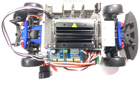
To clarify, I am not referring to the LEDs that you have on the outputs of the multiplexer, I am referring to the yellow indicator LED built into the multiplexer PCB, shown here:

Can you describe the behavior of that yellow LED after you changed your code (in your video it was blinking once per second as I described before)? It would be helpful if you could post an updated video and your updated code as well.
Brandon
sorry, no change same 50% 60-hz. I tested both with and without jumper, no change. By the way, do I want the jumper on or off?
mike
import time
import board
import busio
import adafruit_pca9685

# Create I2C bus
i2c = busio.I2C(board.SCL, board.SDA)

# Create PCA9685 object
pca = adafruit_pca9685.PCA9685(i2c)
pca.frequency = 50  # Set PWM frequency to 50 Hz

# Calculate correct duty cycle
def calculate_duty_cycle(pulse_width, period):
    return min(int((pulse_width / period) * 4096), 4095)

# Set valid master signal for SEL pin on multiplexer
def set_master_signal():
    pulse_width = 1.0  # Master signal pulse width < 1.6 ms
    period = 20  # Period in seconds (50 Hz frequency = 20 ms period)
    duty_cycle = calculate_duty_cycle(pulse_width, period)
    pca.channels[1].duty_cycle = duty_cycle
    print("Master")

# Set valid slave signal for SEL pin on multiplexer
def set_slave_signal():
    pulse_width = 2.0  # Slave signal pulse width > 1.6 ms
    period = 20  # Period in seconds (50 Hz frequency = 20 ms period)
    duty_cycle = calculate_duty_cycle(pulse_width, period)
    pca.channels[2].duty_cycle = duty_cycle
    print("Slave")

# Blink LED on a given channel
def blink_led(channel):
    for _ in range(5):  # Blink LED 5 times
        pca.channels[channel].duty_cycle = 4095  # LED on
        time.sleep(0.5)
        pca.channels[channel].duty_cycle = 0  # LED off
        time.sleep(0.5)
    print(f"Finished blinking LED on channel {channel}")

# Alternate SEL signals and blink LEDs
def alternate_sel_signal():
    while True:
        set_master_signal()
        blink_led(1)  # Blink LED on master channel
        time.sleep(7)  # Master signal for 7 seconds
        set_slave_signal()
        blink_led(2)  # Blink LED on slave channel
        time.sleep(7)  # Slave signal for 7 seconds

# Run the SEL signal function
alternate_sel_signal()
Hello.
Whether you should or should not use the optional FAILMODE jumper depends on what you want for your application. How the board behaves with and without the FAILMODE jumper is described on the product page overview and in the Components of the 4-Channel RC Servo Multiplexer section of the user’s guide. Whether or not you are using it should not be relevant here.
Can you look at your signal to SEL with an oscilloscope and post captures of that so we can confirm it is actually behaving as expected?
- Patrick
Brandon,
I suspect that the module might be defective. As you can see in the video, it behaves oddly. The code it pasted below:
from adafruit_pca9685 import PCA9685
import board
import busio
import time
import signal
import sys

# Create I2C bus
i2c = busio.I2C(board.SCL, board.SDA)

# Create PCA9685 instance
pca = PCA9685(i2c)
pca.frequency = 50  # 50Hz frequency PWM
pca.channels[0].duty_cycle = 2048
pca.channels[4].duty_cycle = pca.channels[0].duty_cycle # monitor with Audacity.

# Ensure both LEDs are off
pca.channels[1].duty_cycle = 0
pca.channels[2].duty_cycle = 0
pca.channels[3].duty_cycle = 0
# time.sleep(3)

# Initialize LEDs
def initialize_leds():
    pca.channels[1].duty_cycle = 0  # OFF for OUT1 (none)
    pca.channels[2].duty_cycle = 0  # OFF for OUT2 (slave)
    pca.channels[3].duty_cycle = 0  # OFF for OUT3 (slave)
    #pca.channels[4].duty_cycle = 0  # OFF for OUT4 (master)
    print("LEDs Off")

initialize_leds()

# Cleanup function on Ctrl+C
def signal_handler(sig, frame):
    initialize_leds()
    sys.exit(0)

signal.signal(signal.SIGINT, signal_handler)

# Function to blink LEDs
def blink_leds():
    while True:
        print('while = True')
        # set_default_valid_signal()
        pca.channels[1].duty_cycle = 4096 # Turn ON Master LED, M4 to OUT4
        print("master 1 ON")
        time.sleep(1)
        pca.channels[1].duty_cycle = 0
        #print("master 1 OFF")
        #time.sleep(1)

        # set_default_valid_signal()
        pca.channels[2].duty_cycle = 1024  # Turn ON Slave LED, S1 to OUT1
        print("slave 2 ON")
        time.sleep(1)
        pca.channels[2].duty_cycle = 0
        print("slave OFF")
        # time.sleep(1)

        pca.channels[3].duty_cycle = 2048  # Turn ON Slave LED, S1 to OUT1
        print("slave 3 ON")
        time.sleep(1)
        pca.channels[3].duty_cycle = 0
        print("slave OFF")
        # time.sleep(1)

        # Ensure both LEDs are off
        #pca.channels[2].duty_cycle = 0
        #pca.channels[1].duty_cycle = 0
        #print("Both LEDs OFF")
        #time.sleep(1)

# Run the test
blink_leds()
thanks,
mike
ps video failed to upload, but I sent an email yesterday.
I received your email with the video; thank you for letting me know.
It is still hard to follow all of your connections, but it looks like the LED on the multiplexer is now indicating that the SEL input is valid and in the “off” position, meaning the master signal should be controlling the outputs. It also looks like you are only providing 1 master input signal (the one connected to the blue LED, which seems to be behaving as expected based on your code). The other master inputs are floating, so that probably explains the odd/unpredictable behavior you’re seeing on the outputs. If you want those outputs to be low when the master inputs are active, you should either drive the respective master inputs low or add pull-downs to them.
Brandon
Brandon,
Thank you for your help and pardon my ignorance. I do not understand what it means for the master to be ‘off’. Is the off/on determined by SEL wired to the pca.channels[0]? Does ‘off’ mean only the master is passed; does this imply that ‘on’ means the slave is passed? How do I set the slave to be passed to out? Is this done by decreasing the duty_cycle below 1696? I have read the manual, but I do not understand the implied meaning of many points discussed.
I did not intend the slave to float. The pca9685 channels[2] and channels[3] are wired to s2 and s3, with leds on out2 and out3. Is that how it works?
I have pca.channels[1] wired to M1 and channels[4] to M4, with leds on out1 and out4.
# Code:
from adafruit_pca9685 import PCA9685
import board
import busio
import time
import signal
import sys

# Create I2C bus
i2c = busio.I2C(board.SCL, board.SDA)

# Create PCA9685 instance
pca = PCA9685(i2c)
pca.frequency = 50 # 50Hz frequency PWM
pca.channels[0].duty_cycle = 106*16 # 1696 duty cycle

# Ensure both LEDs are off
pca.channels[1].duty_cycle = 0
pca.channels[2].duty_cycle = 0
pca.channels[3].duty_cycle = 0
pca.channels[4].duty_cycle = 0

# Initialize LEDs
def initialize_leds():
pca.channels[1].duty_cycle = 0 # OFF for OUT1 (master)
pca.channels[2].duty_cycle = 0 # OFF for OUT2 (slave)
pca.channels[3].duty_cycle = 0 # OFF for OUT3 (slave)
pca.channels[4].duty_cycle = 0 # OFF for OUT4 (master)
print("LEDs Off")

initialize_leds()

# Cleanup function on Ctrl+C
def signal_handler(sig, frame):
initialize_leds()
sys.exit(0)

signal.signal(signal.SIGINT, signal_handler)

# Function to blink LEDs
def blink_leds():
while True:
pca.channels[4].duty_cycle = 2048 # Turn ON Master LED, M4 to OUT4, blue
print("master 4, blue ON")
time.sleep(1)
pca.channels[4].duty_cycle = 0

pca.channels[3].duty_cycle = 2048 # Turn ON Slave LED, S3 to OUT3, red
print("slave 3, red ON")
time.sleep(1)
pca.channels[3].duty_cycle = 0

# set_default_valid_signal()
pca.channels[2].duty_cycle = 2048 # Turn ON Slave LED, S2 to OUT2, green
print("slave 2, green ON")
time.sleep(1)
pca.channels[2].duty_cycle = 0

pca.channels[1].duty_cycle = 2048 # Turn ON Master LED, M1 to OUT1, white
print("master 1, white ON")
time.sleep(1)
pca.channels[1].duty_cycle = 0
# time.sleep(1)

# Run the test
blink_leds()
Thanks,
The board works by reading the RC input on the SEL pin and using that to determine which inputs (master or slave) get passed to the output pins. By default, the threshold pulse width is approximately 1700μs; the switch will be activated when the pulse width received on the SEL pin is above this threshold and inactive when the pulse width is below it. So, for example, when you send a pulse width shorter than 1700μs to the SEL pin, the switch is inactive and the board passes the master signals (M1-M4) to the respective outputs (OUT1-OUT4). When the pulse width signal is longer than 1700μs, the switch is active and passes the slave signals (S1-S4) to the respective outputs (OUT1-OUT4).
It sounds like you might have been expecting the board to work differently. Can you explain what you are trying to do and how you wanted to use the board?
Brandon
I am learning about AI through the jetracer project.
The multiplexer function is to switch between RC control and autonomous control.
I am unable to get the multiplexer into slave mode, so I am experimenting with LEDs to learn how to do it. Evidently, I am missing a key bit of knowledge. mike
Unfortunately, I am not very familiar with the jetracer project, but the RC multiplexer should be a good choice for switching between RC control and autonomous control.
As I described in my previous post, the signal on the SEL pins determines whether the master or slave inputs are used on the output pins. It looks like your SEL pin is connected to the Adafruit PCA9685 board, but I do not see any code for controlling that signal in your latest program.
If all you’re trying to do right now is get the multiplexer to successfully switch between the master and slave modes, I recommend simplifying your setup and code by removing all of your connections to the multiplexer (including the LEDs on the outputs) aside from your SEL signal, ground, and power (to the VM rail). Then, you can use some very simple code that just changes the SEL signal and look at the multiplexer’s onboard LED to see what state the outputs are in (i.e. slave or master).
Brandon
Brandon,
I must be missing something. I tried the following this morning.
Code:
import time
import board
import busio
from adafruit_servokit import ServoKit
from adafruit_pca9685 import PCA9685

# Create I2C bus
i2c = busio.I2C(board.SCL, board.SDA)

# Create PCA9685 object
pca = PCA9685(i2c)
pca.frequency = 50 # Set PWM frequency to 50 Hz

# Create ServoKit object
kit = ServoKit(channels=16)

def set_slave_signal(pulse_width):
if pulse_width > 1.696:
print('pass slave')
else:
print('pass master')
period = 20 #convert to sec to ms. Period in seconds (50 Hz frequency = 20 ms period)
duty_cycle = int((pulse_width / period) * 4096)
print(f"duty_cycle= {duty_cycle}")
pca.channels[0].duty_cycle = duty_cycle # Assuming SEL is on channel 0

def blink_ledv2(channel, pulse_width, duration=0.5, cycles=7):
print(f"blink_ledv2{channel, pulse_width, duration, cycles}")
set_slave_signal(pulse_width)
for _ in range(cycles):
kit.servo[channel].angle = 0 # Turn LED on at 0 degrees
time.sleep(duration)
kit.servo[channel].angle = None # Turn LED off by setting angle to None
time.sleep(duration)
print(f"Finished blinking LED on channel {channel}")

blink_ledv2(channel=1,pulse_width=2) # >1.696ms switch activate, pass slave to out
blink_ledv2(channel=4,pulse_width=1) # wired to master
You did not see code controlling SEL? The pca9865 ch0 is wired to SEL. Is more needed than setting the pulse width and period? I consistently use code: pca.channels[0].duty_cycle. The code is simple but fails to work.
Please show me simple code so that I can get past this mental block.
Thank you,
mike
Thank you for the clarification; it looks like you only set the duty cycle on channel 0 at the beginning of the code in your previous post, and never changed it, so there is no reason to expect the outputs to change. Your new code looks better, but still has a lot of additional things that are complicating it, and it is not clear from your description how it “failed”. Could you simplify things by doing the test I suggested previously:
- Remove all of your connections to the master and slave inputs as well as the LEDs on the outputs (i.e. only leaving your connection to SEL, power, and ground).
- Run a simple code that switches the SEL signal so it alternates between activating and deactivating the multiplexer.
- Monitor the LED on the multiplexer while the code runs.
For example, while running a code like this, you should see the LED on the multiplexer invert its behavior every 5 seconds (i.e. it should first be on most of the time and blink off once per second, then switch to being off most of the time and blinking on once per second):
import time
import board
import busio
from adafruit_pca9685 import PCA9685

# Create I2C bus
i2c = busio.I2C(board.SCL, board.SDA)

# Create PCA9685 object
pca = PCA9685(i2c)
pca.frequency = 50 #frequency in Hz

def set_sel_signal(pulse_width):
    period = 20 #period in milliseconds
    duty_cycle = int((pulse_width / period) * 4096)
    pca.channels[0].duty_cycle = duty_cycle

master_pulse_width = 1 #in milliseconds
slave_pulse_width = 2 #in milliseconds
duration = 5 #in seconds
while True:
    set_sel_signal(slave_pulse_width)
    time.sleep(duration)
    set_sel_signal(master_pulse_width)
    time.sleep(duration)
Brandon
Brandon,
Thank you for the code; however, the results are the same as with my code. There is no change that I can see in the blink pattern of the yellow, internal led. If you look at my code the duty cycle is changed in the set_slave_signal() function, which is called by the blink_ledv2() function. I tried it with and without the jumper.
def blink_ledv2(channel, pulse_width, duration=0.5, cycles=7):
print(f"blink_ledv2{channel, pulse_width, duration, cycles}")
set_slave_signal(pulse_width)
I think my module is defective. Can you please send another one?
mike
Just to clarify, what blinking pattern did you see?
Please try doing the two steps described in the “General Configuration Procedure” section of the RC Switch user’s guide to reset the multiplexer to its default threshold setting, just in case it somehow got changed on accident. After that, if you test it and the behavior has not changed, please email us with your order information and a reference to this thread.
Brandon