We are a group of college students in AAlesund, Norway.
We are working with a swarm of 3PI robots(10stk), and have some questions about what I/O lines we should use.
On one scenario we want to use the light sensor in addition to the IR beacon and the easy radio ER400TRS. Is this even possible?
Things we don’t need is LCD, buzzer and LEDs.
Can we make this work?
Also can we use ICSP programming lines PB3, PB4, PB5 to something else than just programming the 3PI?
That sounds like a very interesting project! The easiest way for you to connect a large number of peripherals to your 3pi would be via the expansion kit without cutouts, which would give you easy access to the LCD pins. Additionally, have you considered using the 3pis as serial slaves that are controlled by another MCU? You could then connect some or all of your sensors to this secondary, master microcontroller.
If you want to do everything with just the I/O available on the 3pi, you should pay careful attention to the 3pi schematic to see how the ATmega168 I/O lines connect to the 3pi hardware. For example, you can see that if you remove the LCD, the LCD control pins PB0, PD2, and PD4 become completely free for your own use. The LCD data pins (PB1, PB4, PB5, and PD7) can be used, but you need to make sure that their alternate functions do not conflict with whatever you connect to them (pins PB1, PB4, and PB5 connect to the user pushbuttons, and PD7 connects to the green user LED). Note that PB4 and PB5 are also programming lines, so you shouldn’t connect anything here that would interfere with programming. The last programming line (PB3) doubles as a motor driver input, so you won’t be able to connect anything here without imparing motor control. Lastly, the 3pi doesn’t require the buzzer, so you could remove it to gain access to one more I/O line (PB2) if you really need to.
So in summary, pins PD0 and PD1 are completely free digital I/O lines that can be used for general-purpose I/O or for TTL serial communciation. Pins PC5, ADC6, and ADC7 can be freed from 3pi hardware by removing their respective shorting blocks. PC5 can be used as an analog input or a digital I/O, and ADC6 and ADC7 are dedicated analog inputs. Pins PB0, PD2, and PD4 become completely free digital I/O lines once you remove the LCD, and pins PB1, PB4, PB5, and PD7 are digital I/O lines that you can use for certain applications if you are careful not to cause conflicts between them and their alternate functionality. Lastly, pin PB2 can become a completely free digital I/O line if you remove the buzzer.
Does this sufficiently answer your questions? Good luck with your project; we’d love to hear more about it as it progresses!
Thanks! That was the answer we were looking for. The IR Beacon require 4 digital outputs right? And we believe that the Easy Radio requires 1 Digital input and 1 Digital output for data and maybe an busy output signal. So then we need 7 digital I/O. The ones we’ve thinking about using is: PD0,PD1,PD2,PD4,PB0,PC5 and maybe PD7. We are also going too look into the serial slaves, but which secondary MCU do you recommend? ATmega168?
We will try to post the progress about the project here.
If you go with a secondary microcontroller, I recommend you choose whatever you’re already most comfortable programming. If you don’t have a favorite microcontroller, then I’d recommend an ATmega168 (either an Arduino or something like our Baby Orangutan) so that you only need to familiarize yourself with a single microcontroller architecture in order to program both it and your 3pi.
If you just go with the 3pi by itself, you will probably want to connect your Easy Radio to the 3pi’s UART pins PD0 (RX) and PD1 (TX). Your choice of beacon connections to PD2, PD4, PB0, and PC5 seem like good ones.
I haven’t read all of this thread carefully, but if you are thinking about using our IR beacon, please note that the full units we provide work only in pairs. You could reprogram them with a different protocol, in which case you could also design a different I/O protocol and possibly save yourself some I/O lines.
Hi!
Oh. We didn’t think about that. So this means we need to make our own protocol and download it on to the IR beacon? Do you know if someone has done this before? Do you have a guide to do this, since we are not completely sure how to?
We want to use the IR beacons in three different cases. In the first case we want to have several bots finding and following each other. The way we want to do this is, based on the bots gets hes own rank and he follows the other bot which has a higher rank… So If bot one and two finds each other, than number two will follow number one. When they meet number three he will follow number two and so on… this way they will eventually make up a line of bots.
Second case is about simulating an intersection where we want the bots to follow basic traffic rules, such as keeping a good distance of the bot a head. And stopping or slowing down for the bots that comes from the right.
Let us know if there is something you don’t understand…
We do not have a guide for developing your own beacon protocols. The processor on the beacon is a Microchip PIC16F630, for which you can find documentation online. The challenge will be in developing the protocol since you don’t inherently get any direction or range information out of the IR detector modules, and you’ll need to make sure that all the units don’t just try to transmit at the same time.
I think I generally understand what you are trying to do, but I think you might not realize how much you are expecting of your sensor system. Making a system where robots can identify each other and the distances and directions to each other will probably be the majority of your project: once you have that, the rest should be a relatively simple demonstration of that system.
Where to start?
If we understand you correctly, we need to reprogram the IR beacons Microchip PIC16F630 with our own set of protocols right? If that’s the case, we are not sure how to do this. What do we need to program the Microchip PIC16F630? i stumbled upon the Microchip’s program MPlab is this what we need? And also do we need a programmer, like the baby-o that is needed by the 3pi?
If this is not the case at all, and all we need is to define the protocol on the 3pi?
We also made a list of what the Ir specification must be:
robots must be able to detect signals from up to 9 other robots (10 all together, but 8 could be sufficient )
robots must be able to detect signals within 1/10th of a second
robots must not detect their own signal
robots must have an unique ID
the signal should only work within line-of-sight
the signal must be detectable from 6 inches to 20 feet
the signal must not interfere with any other sensor
We didn’t completely understand what you are trying to say here… Can u explain better?
You would need a PIC programmer, such as Microchip’s PICKit (they’re probably up to version 3). By the way, the 3pi does not need a Baby Orangutan; rather, they both need a ATmega168 programmer, such as our Orangutan programmer.
In looking over my previous comment, I really don’t understand what you don’t understand about it. Let’s break it up:
It will be difficult, because:
The IR detector modules don’t tell you how far away the transmitter is,
The IR detector modules don’t tell you the direction to the transmitter, and
You can’t see multiple signals at once, so you can only have one transmitter transmitting at a time.
What you are trying to design (or find) is complicated, and some of your requirements are a combination of useless and impossible (e.g. “the signal must not interfere with any other sensor”). Have you looked at the datasheet for the sensor and looked into any IR remote control protocols?
Over to a different problem. I’m trying to make two 3pi bots with IR beacons work together, and have stumbled across a couple of weird problems.
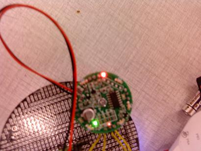
First problem: I wrote a simple program that sets PC5, PD2, PD4 og PB0 as inputs (connected to the ir beacon), and drives the 3pi forwards. 3 of the sensors on the beacon is working properly, but the one connected to PB0 is not working properly. The led that signals that it is recieving is constantly on, although only half as bright as the other 3 leds when recieving.
#include <pololu/3pi.h>

int main()
{

	DDRC&=~(1<<PC5);//set PC5 as input
  	DDRD&=~(1<<PD2);//set PD2 as input
	DDRD&=~(1<<PD4);// set PD4 as input
  	DDRB&=(1<<PB0);//set PB0 as input

	while(1)
	{
		if(!(PINC&(1<<PC5))){
         //north detected, do nothing
		}
      	if(!(PIND&(1<<PD4))){
         //east detected, do something
		 	set_motors(20,20);
			delay_ms(2000);
			set_motors(100,100);

    	}
      	if(!(PIND&(1<<PB0))){
        // south detected, do nothing

		}
      	if(!(PIND&(1<<PD2))){
         //west detected, do nothing
      	}

	}

	return 0;
}
Second problem: When i tried to add “line following” to the code (from the line following example), the other 3 sensors connected to PC5, PD2 and PD4 are also on constantly, and the IR beacon is not transmitting any signal to my other beacon.
Do the beacons work when you don’t have them connected to the 3pi? If so, you’re probably setting some of the I/O lines connected to the beacons to outputs, which is not good (be careful when you add code that might think something else (like the LCD) is connected). Another thing to consider is the power arrangement. How are you powering the beacon? Do you notice a change when your robot uses more power (e.g. running the motors)?
Since you’re having trouble with PB0, take a careful look at the line of code that sets up that port:
DDRC&=~(1<<PC5);//set PC5 as input
DDRD&=~(1<<PD2);//set PD2 as input
DDRD&=~(1<<PD4);// set PD4 as input
DDRB&=(1<<PB0);//set PB0 as input
The line for PB0 is different from all of the others! Fix that and you will have a completely working beacon - at least until you run the line following code.
Now, the example line following code uses both the LCD and port PC5, so you’ll have to modify it to get all of those pins to work. If you turn off the LCD code, the only pin you’ll have a problem with is PC5; and that could easily be replaced with PD0 or PD1 in your application, which are totally free.
Thanks for the reply. I changed the PB0 to input, but sadly it’s still not working
I changed the code to only set the four pins as inputs like the following, but the sensor connected to pin PB0 still is on constantly.
#include <pololu/3pi.h>

int main()
{

   DDRC&=~(1<<PC5);//set PC5 as input
     DDRD&=~(1<<PD2);//set PD2 as input
   DDRD&=~(1<<PD4);// set PD4 as input
     DDRB&=~(1<<PB0);//set PB0 as input


}
The picture is crappy, but maybe you can see the problem. The north sensor is picking up another beacon, while the south is just on like that constantly, only half as bright as the others, as you can see in the photo.
Edit:
I have now tested the PD7, PD0 and PD1 as inputs. I can’t get PD7 to work at all, PD1 gets high constantly and the red user LED underneath the 3pi gets high. It looks like PD0 is working though. Is there a trick to disable the red/green user LEDs?
You still haven’t confirmed that the beacon is working correctly when it’s not connected to anything else. That’s an important data point to have so that we can be sure the problem is just with your connection or software. Unfortunately, there is no way to disconnect the LEDs short of desoldering them. The LED most likely is the problem on PD7 since the beacon output is normally high and therefore you get the two LEDs (one on the beacon, the other on the 3pi) from power to ground.
In any case, you should test the parts independently. First, test the beacon by itself, as I’ve been saying. Then, use something like a 470-1k resistor to connect your various 3pi inputs to ground and 5V to make sure that they are working. If you cannot see the appropriate activity on the inputs, DO NOT connect something else since you might have the pins configured as outputs and could destroy something. Bring the two parts together only when you have them working independently.
Also, I’m not sure if you are showing me your whole code or not, but it’s a very bad idea to let your main() function reach the end - you should always have a statement like
while(1);
as the last line of main() so that the AVR doesn’t start executing random code.
I actually didn’t quite understand how i could use this to test the inputs, how do i get feedback on them working when i only connect a resistor from input to ground or 5V?
After some testing, it seems pin PB0 is working properly, even if the led on the beacon is halfway on constantly. I altso tested the beacon on PB5, PB1, PD4 and PD2 and it works great.
Edit: Now it seems that I have another problem, while flashing the 3pi, the 3pi turned it self off and now I can’t get to flash it. The error I get is:
Can you check that your batteries are charged? The only time the 3pi should ever turn off is if the batteries are low - and you should never be programming it with low batteries, because you risk corrupting the 3pi’s fuse settings.
If the 3pi loses power during programming, the fuses on the microcontroller can occasionally get corrupted. You should never program the 3pi if the batteries are low!
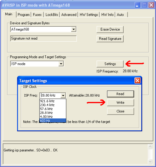
If you are using AVR Studio, can you try to change the ISP frequency of the programmer to something much lower, like 600 Hz? You can do this using the Main tab of the AVRISP dialog box–click the Settings button, select 603 Hz, and then click the Write button.
After this is done, try to read the device signature (the Read Signature button under the same tab). If it works, let me know, and I will guide you through restoring the fuses to their original states. If it doesn’t work, you will need to send the 3pi back to us for repair (send us an email and we’ll give you an RMA number).
Don’t forget to change the frequency of the programmer back to something faster, such as 921.6 kHz, when you’re done!