I am looking to use the 3pi+ for a robotics class with a software focus. Ideally students would work their way up to a potential fields algorithm using the encoders, gyro, acc and compass for tracking location, angle, maintaining position and advancing towards a goal. Then 1 or more ultrasonic sensors for identifying the obstacles that represent the repulsive forces.
I am curious if I can add ideally an ultrasonic sensor and a servo to the robot ideally without soldering, is it possible for example to reuse the pins on the lcd header for this? Does anyone know of an example online of someone using ultrasonic sensors with the 3pi+? I am not seeing much of anything I believe because the robot is relatively new.
PS: I did look here: https://www.pololu.com/docs/0J83/5.8
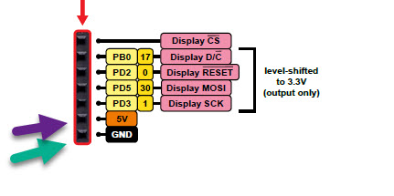
And from what I am seeing I do have 5v and gnd on the LCD header, along with pins 13, 14, 17 and 30… I am not including 0 and 1 since I believe they are serial but they might be a possibility as well.
If you do not need all the features of the 3pi+, you should be able to add an ultrasonic sensor and servo without soldering. The Adding electronics section of the 3pi+ user’s guide has details about what pins can be freed-up by sacrificing various features, the possible uses (including PWM output) for each pin are listed in the table in the Pin assignments section just before that, and the Expansion headers section shows what pins are available on which headers.
For adding a servo you could use the Arduino servo library, but since it uses Timer 1 by default and the 3pi+ already uses that timer for its motors, you would need to modify the library. Instructions for doing that can be found in the Controlling a servo section of the Romi user’s guide. Our Romi robot also uses the ATmega32u4 and Timer 1 for its motors.
If you have not picked out an ultrasonic sensor yet, you might consider our Maxbotics sensors. They could be used with the 3pi+ via analog or serial. If you have questions about connecting a specific sensor and you post more information about it, I would be happy to help.
Thank you very much for your reply, it has been very helpful. I think my biggest challenge is staying on the lcd header so that students can make reliable connections without soldering. I am also trying to avoid using Arduino pins 0 and 1 so that the students can use Serial.println() to debug.
So on the lcd that leaves pins: 13, 14, 17, 30. The “Freeing up I/O pins” section only mentions pin 14 out of this group:
“If you have removed the LCD and do not need to use button A, this frees up pin 14 (PB3). Pin 14 is capable of digital input and output.”
I see that there is a note about pins 13 and 17 here:
“Be careful about connecting electronics to pin 13 (PC7), pin 17 (PB0), and PD5. These pins are used to control the LEDs on the 3pi+ 32U4. All three of these pins are controlled as outputs by the bootloader. Pin 17 (PB0) and PD5 are used as RX and TX indicators, so if you are sending or receiving data over USB then the Arduino USB code will drive those pins in its interrupt service routines while your sketch is running.”
Am I understanding correctly that I can use these pins so long as the USB connection is not actively being used while the program is running (but it would not effect the usb connection when flashing a sketch?)
I don’t see any mention in the document of pin 30 and whether on not it is safe to use, I only see on the chart mentioning UART clock. Is this okay to use?
Just a note: I was able to get the US sensor I had laying around (HC-04) working on pin 17 and 30 without issue.
Now to play with the servo, I have read up on the timer modification you mentioned. The other challenge will be power though, I am following this correctly:
" * 5V is the output of the TPS2113A power multiplexer circuit which is connected to R5V by default, but switches to 5 V USB power if R5V is too low."
The 5v connections (like the one on the lcd header) will use the batteries when the switch is on and provide enough amps for something like an SG90 servo (5v i think 550ma) but I only have the 1 5v pin in the lcd header. Can I share it with the ultrasonic sensor?
The 3pi+ uses an ATmega32U4 like the Arduino Leonardo, so pins 0 and 1 are connected to Serial1 (the TTL serial interface) and not used for the serial monitor. You are right that pins 17 and 30 (which is the same as PD5) are fine to use as long as your program doesn’t communicate over USB, but the Arduino serial monitor uses USB. Given all of that, pins 0 and 1 might be better choices.
As you quoted, the on-board 5V regulator from the batteries will generally supply the 5V line. The output of that regulator can supply about 0.7A. That is likely enough for your single servo and sensor and it should be fine to power them both from the same pin on the LCD header.
Thank you again, you found the piece I was missing, 0 and 1 are not used by the serial monitor on the 32u4. That is perfect.
I am getting one more to experiment with (standard, my first is a turtle) but it seems like this will be a perfect platform. Just going to play around with ideas to mount the servo.
I just wanted to follow up and let you know that I have a version 1 setup working on a turtle with 2 US sensors. Will be adding the servo to the new standard edition shortly. I made a video for my students: https://youtu.be/96FuKrPOUOo and pseudo-reviewed the 3pi+ in it. Thought you might be interested, great platform, thank you for the help!
Thanks for sharing that video! The intro with the 3pi+ avoiding obstacles and cats is great, and the entire thing is really well produced and thorough. We look forward to seeing more in the series!
Heloo, I was trying to follow the exact same instructions shown in the videos to do an autonomous robot for my class, I bought the pololu 3pi+32U4 but I incorrectly chose the OLED version, and now no mather what I cannot connect the ultrasonic sensor following the instructions the user bg305 has in his youtube chanel, more specifically this video https://www.youtube.com/watch?v=JXIbxX-Wtgw&t=1026s .
I’ve tried using all the pins configurations, tried with three different HC-SR04 just in case the sensors were defective, tried the sensors with another Arduino setup and they work perfect, tried the same code over and over, watched the video several times, still, I cannot connect the ultrasonic sensor no matter what. the VCC and the GND are pretty clear and I use them as is, the other two wires for the TRIG and ECHO i’ve tried in every other of the pins, 17/30 and 1/0 as well.
Could you please advice how could I connect the ultrasonic sensor and if its not possible just let me I can buy another device or let me know if I can change the one I bought from you guys to the LED version ?
Unfortunately, as indicated by the part of the diagram you posted, the pins on the OLED header are limited to only being outputs (due to the level shifting hardware on the board). So, you will not be able to use them as an input to read the signal back from the ultrasonic sensor (i.e. for ECHO_PIN). You can access those pins before the level shifting circuitry at different locations on the board, as shown in the diagram in the “Expansion headers” section of the 3pi+ 23U4 user’s guide; however, please note that pins 30 and 17 are also used for button B and button C respectively, so you might consider using other pins instead. For example, if you’re not using the line sensors, you can use any of the pins that are normally used for those (i.e. pins 12, 18, 20, 21, and 22), which are all accessible from the expansion area near the front of the robot. You can find more information about freeing up I/O pins in the “Adding electronics” section of the 3pi+ 23U4 user’s guide.