Hi there,
my first 3pi is on its way - right now not autonomously
For an upcoming project I would like to create a prototype which follows a path on a LCD Screen: the path would be black pixels and the background white (or vice verse). In this case the screen would not emit any IR light, but just visible light.
From the specs I can see the see, that the phototransistor are working with IR light. Visible light will be filtered, right?
So… is there an easy way to change the IR to “normal” phototransistors ?
That sounds like a pretty exciting project, and we would be love to hear more about it and how it progresses!
You might start out by just trying the existing sensors to see what kind of readings they give you (I would be interested in hearing if the 3pi’s sensors just work). Replacing them, if you have to go that route, will not be easy since those sensors are surface-mount components. However, if you are willing to undertake that task, then you can look at our simplified schematic (which is available on the 3pi product page under the resources tab and the 3pi user’s guide) to understand how the QTR sensors are connected and work from there to figure out how to replace them with your own sensors. We do not have any specific recommendations for alternative visible light sensors or how to do the modifications.
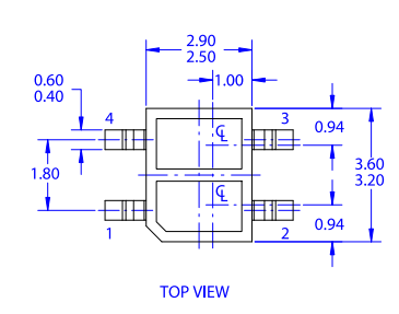
We do not commit to a particular component, but if you want to be adding your own phototransistor, it seems like all you need is the footprint. Here is the package drawing from the Fairchild/On Semi QRE1113GR:
Pin 3 is the collector and pin 4 the emitter. (In case it’s hard for you to make out the beveled corner, the phototransistors are more toward the inside of the robot, and the emitters are closer to the edge.)