Hi,
I’m new to the forum and have a brand new 3pi robot running under Win7 AVR Studio 4. Software install went fine. Demo programs didn’t work for line following (simple or PID) and maze.
With some add’l lines of code I get these readouts from the “read_line(sensors, IR_EMITTERS_ON);” routine: 1500, 1750, 2000, 2250, 2500 if left most sensor over line to right most sensor over line.
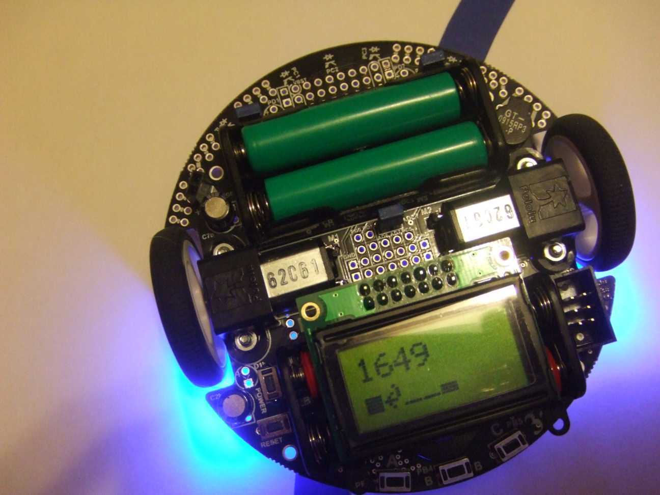
When I use the “display_reading(sensors);” routine, I get “random” results, but never a bar representation of sensor position over the line (1/2" dark blue electrical tape on white foam board). Sometimes I even see a “carriage return” kind of an arrow instead of a bar.
So all this led to review the hardware. For that I found on this forum a thread that dealt with hardware troubleshooting of the sensors / robot (here: https://forum.pololu.com/t/broken-ir-sensors/3672/1 )
I did the testing with these results (btw, battery readout was 5124mv):
With the 3pi off, can you verify that there is continuity between the pad labeled VBOOST in the above diagram and any other VBOOST access point on the board? - OK continuity
Can you also check to see if there is continuity across all five LEDs (because the LEDs are diodes, your multimeter’s continuity check will only work in one of the two possible ways you can connect your probes). If not, can you start narrowing it down to find out where the continuity break is? - I get 6000 Ohm on the top and 2200 Ohm on the bottom leeds.
With the 3pi on, can you check to see if the LEDON pin voltage is 5 V? - 4V if the jumper PC5 is off, 0V with PC5 on
Also, can you verify that the region outlined in white in the above diagram really is being connected to ground through the MOSFET - OK continuity
Any suggestions? Does this suggest a broken device?
Are you saying that the return value of “read_line” is correlated with the position of the robot over the line? If so, it sounds like the line sensors are still functioning.
Please try running the 3pi-linefollower example in the Pololu AVR C/C++ Library. Are you making sure that the robot is on a line during the calibration phase so that when it turns back and forth each sensor can be exposed to full blue and full white?
I’m using the program “3-pi-linefollower” from the libpololu-avr/examples/atmega328p library.
The robot is with the sensors on the line during the calibration routine and stops the routine back on the line.
In terms of the the readout values being “1500, 1750, 2000, 2250, 2500 if left most sensor over line to right most sensor over line.” it seems as if the sensors are working. Except that I (and your program) expects values of 0 - 4000 and the hardware test didn’t return the expected values.
What kind of batteries are you using in your 3pi? If they are Alkaline, then 5124 mV would indicate they have discharged a lot, and that could be causing problems.
It is more likely that this is a software problem than a hardware problem. No matter what’s happening in the hardware, the code for taking calibrated readings of the sensors should never return values outside the 0-1000 range, so the display_readings function should always display a valid bar graph character.
Maybe there is something strange happening when you compile or load the program. Could you please use AVR Studio to read the program from your 3pi as a hex file from your 3pi and post it here so I can try it on a working 3pi here? It’s important to actually read the program from the 3pi because there might be something wrong with the process you are using to program the 3pi.
Also, could you try loading the HEX file below onto your 3pi and see if it works?
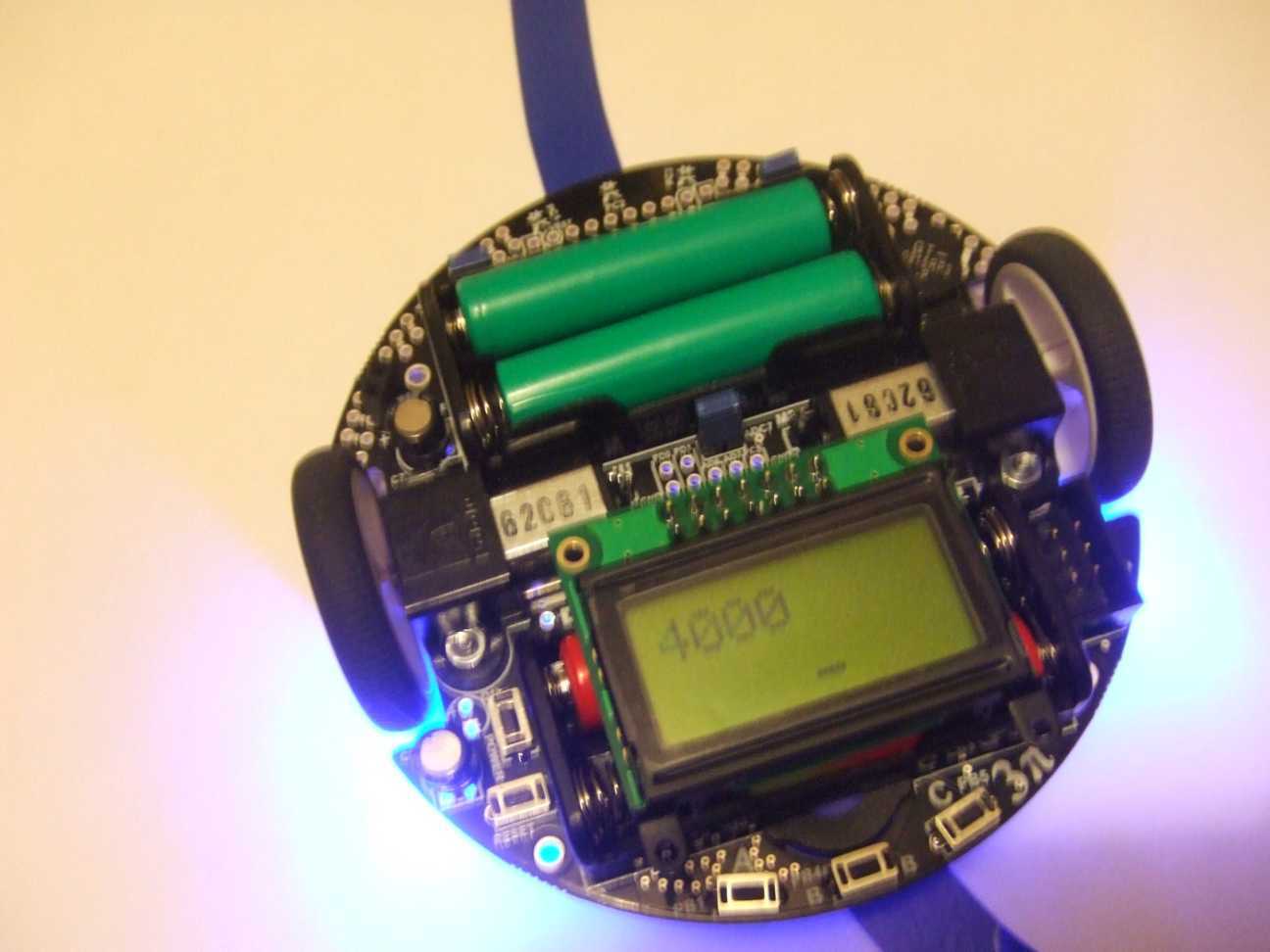
This file came with the download for our AVR Library. If it doesn’t work, could you please post a picture here showing the strange characters on the LCD while running this program? Your picture should show the whole 3pi so we can see where it is on the line.
Recharged the batteries and now get 3,264mv with 4 of Pololu’s “generic rechargeable AAA NiMH battery with a capacity of 900 mAh”.
Loaded your hex file and get the same failure to follow the line. Calibration seems to work OK, 3pi leaves the line after the first 2-3 inches. Attached is YOUR hex file read back from my 3pi. This program doesn’t generate the funky arrow characters. But I believe it’s giving a wrong readout (4000 and no bars while squarely on the line - after the calibration run - see attached picture). iRobot_Troubleshooting.zip (132 KB)
Please also see attached my demo program (source code and hex code read back from my 3pi) that generates the funky arrow character in the senor bar graph readout.
A reading of 3264 mV is way too low for charged batteries. Could you use your multimeter to check the voltage of the batteries, just in case there is some problem with the AVR’s measurement? Also, we don’t sell any red batteries, so from your picture it looks like you are not using 4 Pololu batteries.
The two HEX files you sent contain only ones (0xFF) so something went wrong when reading them. What programmer are you using? Did you correctly set the processor to ATmega328P in the AVR Studio 4 STK500 programming dialog box? Maybe you could tell us exactly what filenames you typed and what buttons you pressed to read the HEX file, because something about the reading is not working.
Sorry for not mentioning this before, but as far as I know we haven’t test the 3pi on foam board with a line made with blue electrical tape. If both of these materials have very similar IR reflectance, you will get bad results. Could you try black electrical tape on white paper, or a black Sharpie on white paper? Also, I think 1/2" tape is too thin to work well with the 3pi. We recommend 3/4" in the 3pi user’s guide.
I just tested the 3pi-linefollower.hex that I posted in my last post on a working 3pi robot here. It was able to correctly read a thick line drawn with black Sharpie on standard white paper.
David,
sorry for the confusion. The voltage was a typo. The readout was 5264mv (instead of 3264mv). The 2 red batteries are my second set and have the same specs as your green ones.
HEX file readout - I need to investigate what happened here. I’ll send you new files.
I’ll test 3/4" electrical tape on white paper. I’m not hopeful that that is the solution.
And it doesn’t explain the funky arrow in the bar display. Btw, the arrow position changes with the 3pi on different place over the line.
Volker
PS: I’m traveling and will be out of pocket for the next couple days.
I think the arrows are being caused by some problem in your compilation process. Maybe you are using an old version of our library or an old version of WinAVR. My intent is to make sure that your hardware is OK, and once that is done then try to address the software problems.
And I’ve selected libpololu_atmeg328p.a as the library under the AVR Studio library settings.
Attached one more time the two hex files. I did test them and opened them with the HexEditorNeo and they do look OK (not all hex FF).iRobot_hex.zip (34.1 KB)