This may be ignorance on my part, but I can’t see where I2C’s SDA line is broken out. I was hoping to modify the Arduino code to make it work with this little robot. SCL is on pin PC5 and that is broken out, but not PC4. Would I be better to put an mbed on it?
Unfortunately, PC4 is used by the IR reflectance sensors, so it is not possible to do hardware I2C with the 3pi directly. If you don’t need to do really quick I2C, it should be possible to do software I2C with any two digital GPIO. Adding an mbed would work. However, the I2C ports both already have a use. One is for serial communication with the 3pi, so that one is not usable, and the other is being used for serial communication with an optional wireless module. If you don’t use a wireless module, the I2C on pins 27 and 28 is completely available to you.
Hi Ryan,
Thanks for the update. Since the ATmega328p SDA is on PC4, I’ve been thinking about an hardware hack, is there a gerber/full schematic available? I don’t mind signing a non disclosure if required.
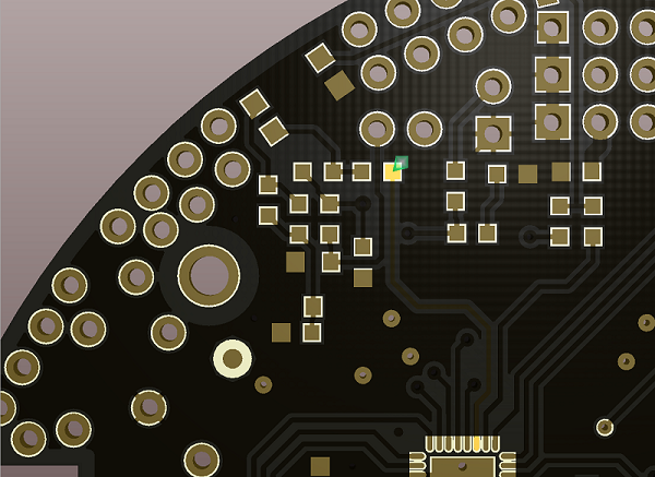
There is a simplified schematic in the User’s Guide and I pointed out the pad connected to PC4 in the image below. It is the one with the green arrow above it.
Thanks again Ryan,
This is the sort of thing I’ve been looking for to see what pads connected to where. Is there a version that covers all of a side?
Yours Simon M.
We don’t want to give out a more complete description of the 3pi routing, but if you have additional specific questions about it, I can see what I can do.