I received a 3pi today. The sample app the comes with the 3pi shows full bars on the qtr sensors. I have run through removing pc5 so the ir leds would not be turned off. If i run my finger by them i see no change in the sensor read out. I also put it on my line course with the same results. I have also loaded the line following sample apps both compiled in avr studio and the pre-compiled hex files. The both show 0 as after the sensor calibration reading with no bars. I am sure i am just missing something stupid. Can anyone shed some light on what maybe my issue here. I have logic probes and a o scope here if someone can lead me to proper test points for the sensors. thanks in advance.
Hello.
Are you exposing all of the sensors to both the surface and the line during calibration? It would also be useful to verify that the sensor emitters are on. Do you have a cheap digital camera around (such as a cell phone camera) that you can use to look at the 3pi’s sensors? You should see the IR LEDs glowing purple on the camera display if they’re on. The second paragraph on this page explains more about looking at IR emitters with a digital camera.
- Ben
Sorry i should have mentioned that. When i hold it up to my cheap web cam :> i don’t see them on. It also does not show on my nikon. I powered up one of your 8 qtr sensor bars and can see them on it. As for exposing them to the line yes i let it do its own self powered sweep for calibration. This is on a standard circle line follow sheet that comes with a nxt or one of my other robots. Every thing else seems to function good. The motors,leds and what not.
Have you had any incidents with your 3pi driving into or over something that could have partially dislodged or knocked a component off of the underside? Can you post a high-resolution picture of the bottom of your 3pi?
The following page shows the 3pi schematic:
Assuming you are not grounding the LEDON pin, it sounds like there might be a break in the path from VBoost to GND that powers the sensors’ IR LEDs. Can you look at each of the reflectance sensors closely to verify that they’re making good contact with all their PCB pads?
- Ben
No incidents when from the box to soldering on the green led. Then to the line following mat. Will get a picture posted when I get home. Will work to follow the traces and make sure power is getting there when i get home also.
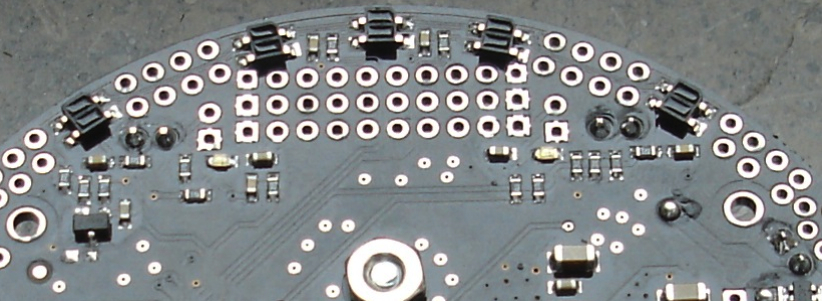
Photos of the bottom.
flickr.com/photos/blackstag/ … 509214682/
I will look at the forward voltages of the leds and what not soon dealing with kids at moment.
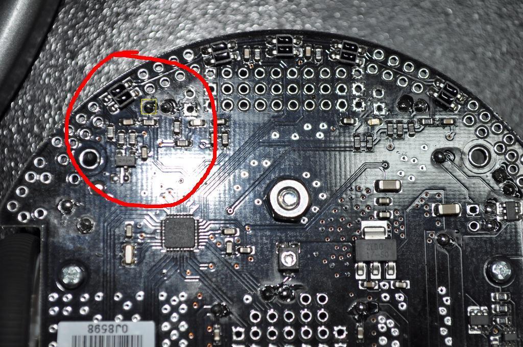
Thanks for the pictures. I don’t see anything obviously wrong from what you posted so far, but I can’t see the sensors well enough to tell if one is partially disconnected. Could you take a few close-up pictures of the circled area I marked in the attached photo? It would help to have one straight on and one or two more from a 45° angle. Also, can you use a multimeter to probe the voltage on the LEDON pin while the board is turned on? The LEDON pin is the one with the yellow box around it in the attached picture.
- Ben
.05 on that pin you asked me to test when in sensor mode. .01 when not in sensor mode. the voltage on pc0-pc4 goes from 9.3 to 6.0 respectively.
flickr.com/photos/blackstag/ … 510158804/
new pictures you asked for i hope they have what you need in them.
The battery meter on the program reads 5637mv.
What do you mean by “in sensor mode”? With the 3pi off and the PC5 shorting block removed, can you use your multimeter to check for a short between the LEDON pin and ground? The pin should be pulled high through a pull-up resistor, which enables the IR LEDs. If it is shorted to ground, this would explain the behavior you’re seeing.
- Ben
I am reading about 17k ohm from ground to pin you told me to check.
sensor mode being when i choose sensors on demo program that comes loaded with it.
If you remove the PC5 jumper, the program that’s running shouldn’t have any affect on the LEDON voltage. Can you measure the LEDON pin voltage again with the PC5 jumper removed and the 3pi powered on? We need to figure out if it is indeed getting grounded somehow (there is a 47k pull-up to 5V on that line, so it should be high when nothing is externally connected to it).
- Ben
2.06 volts.
scratch that 4.78
If you look at the sensors with a camera while you’re getting a reading of 4.78 V (i.e. with the 3pi powered and the PC5 shorting block removed), do you see the IR emitters on?
- Ben
flickr.com/photos/blackstag/ … 511422706/
pictures of it with jumper off. checked it with my cheapo phone camera to make sure my wife camera lens did not have a ir filter. No lights. Took some pictures of the top with the jumper off so you can see it was the right one or not. thanks for working through this with me 
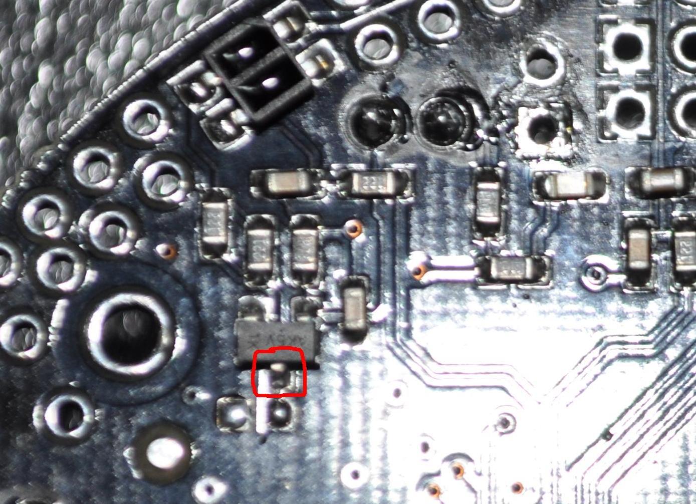
I have one last idea for you to try. It’s hard to tell, but it looks like there might not be a good connection between the PCB and and the emitter-powering MOSFET’s drain (the pin circled in the attached picture). Can you try touching this pin with a soldering iron to reflow the solder and then add a small bit of extra solder? While doing this, make sure you don’t inadvertently create a short between the two unpopulated pads right below this pin. If it still doesn’t work after this, I think we’ll need to take a look at the robot in person. You can contact me directly at ben at pololu dot com for an RMA number.
- Ben
Sounds good will get this done when i get home.
email sent thanks.
Dear Ben,
Exactly I have same problem. First time, the sensors worked properly with good bar reflection by pre installed demo program when I received the 3pi. But when I compiled exactly original Pololu demo program and burned it to 3pi flash then it comes with the 3pi shows full bars on the qtr sensors. Is there any difference between version of per installed programed and sample programs in the website!? I tried many times with different original program codes such as PID follower, simple follower. As he said," If I run my finger by them i see no change in the sensor read out. I also put it on my line course with the same results. I have also loaded the line following sample apps both compiled in avr studio and the pre-compiled hex files. The both show 0 as after the sensor calibration reading with no bars." I checked everything with multimeter seems connections and voltages are Ok but IR emitters are all off when I checked with camera. Please let me know what should I do. Thanks a lot.
Hello.
Can you take a picture of the bottom of your 3pi like the other poster did?
- Ryan
Hi Ryan,
Attached please find the picture. In addition, I checked voltages across QRTs when I removed PC5 jumper which they are the following:
voltage between all QRTs from PC0 -PC4 is 9.12v , V_PC4=1.15, V_PC3=4.92, V_PC2=1.15,V_PC1=1.15,V_PC0=1.15. I don’t know why voltage across V_PC3 is 4.92v. I am at your full disposal for any further information you may need. Thanks a lot.
Best Regards,
Amir