I cant turn on my 3pi robot.
I made some experiments with Sharp distance sensors (used PC5 and ADC7) and, as usually, turned it off by pushing power button. Then I took it to my work table, switched it on but it doesn’t. Just blue LEDs shine and that it is. No standart welcome sound or LCD activity.
Oh, I had some problem once, but its gone itself, I just went to have dinner, came back and it would switch on. So I left it with batteries and without them for a long time, but it doesn’t help.
I checked voltages on Vbat, Vbst and Vcc. (Vbat = 0, Vbst = 9.24, Vcc = 5). But I noticed something strange during my voltage checking. Vbat = 0 at pin located between motors but Vbat = 5.12 at pin located near ADC6 jumper.
Please, help
Can you connect to the 3pi with Atmel Studio (or whatever software you are using to program it)? If so, can you try reprogramming it with the demo program? Also, does anything change when you disconnect your distance sensors?
No, I cant connect to it with my Pololu USB Programmer in AVR Studio. Programmer cant “saw” my 3pi (it blinks red LED instead of yellow), so I cant to program it with any demo or other programs.
Also nothing is change if I disconnect distance sensors.
It seems like your 3pi has somehow been damaged. Could you email us with your sales order information and refer to this thread, to discuss options for fixing the unit?
The problem is that I live very far from USA and shipping 3pi to you will be very expensive (it will be shiper to buy new one). I’d like to fix it in my country.
Maybe I can tell you more information about my robot or made some tests with it.
It would be nice if you send me scheme of top and bottom of PCB so I can check electrical signals at the contacts and traces, because electrical scheme in “3pi User Guige” is not enough.
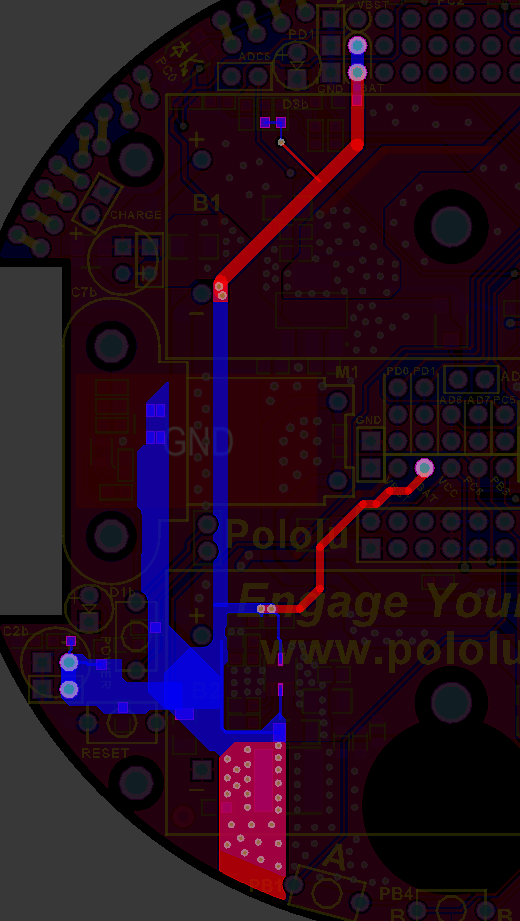
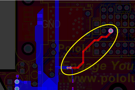
From your description of the programmer behavior, it sounds like it is not detecting 5V on the ISP connector’s VCC pin. I have attached a picture of the 3pi layout with the Vcc net highlighted (red traces are on the top side of the board and blue traces are on the bottom).
Can you probe the ISP connector’s VCC pin with a multimeter to see if it is at 5 V? If it is not at 5 V, can you try to figure out where that connection is getting broken?
It seems very strange to me that you do not measure Vbat between the motors. Maybe you can also probe around and see if that connection is getting broken somewhere. The following picture shows the Vbat net highlighted:
Please let me know if you need any further diagrams. Separately, we might be able to offer you a discount on a replacement if you email us with your order information and reference this thread.
So I solder a wire to Vcc pin, first pin on LCD connector and Vcc pin on ISP
Also I find a bad trace in Vbat electrical net.
But I didn’t repair that one. I didn’t use Vbat voltage and think that I shouldn’t use it in future. And I still get Vbat near ADC6 jumper.
May I left that trace not repaired? Is it (not repaired Vbat pin) influence to the work of my 3pi?
I think that the gumboil, which I used during soldering female connector to the PCB, destroyed that traces. Maybe I cleared PCB bad after soldering.
To now there are no problems but I still testing my 3pi. May I ask you to send me some other diagrams if I’ll find some problem?
Thanks very much for helping in repairing of my 3pi!
I’m very happy to hear you were able to repair your 3pi! Yes, you can leave that Vbat trace unrepaired if you do not need to access Vbat from that center pin (though you might want to fix it if you ever plan on adding a second level to your 3pi, such as by turning it into an m3pi). If you notice any further problems, please let me know and I can supply more diagrams.