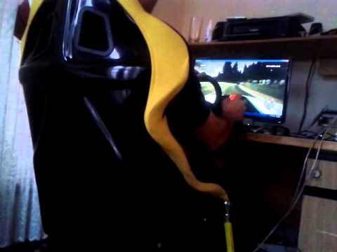
This is the 4th design in a “desk racer” seat mover. As I am not that heavy, a compact unit to suit a person up to 110kg was worked out. The idea being its the same floor area as an office chair and can be slid up to the desk, clamp your wheel and pedals and go racing. Piece of cake.
I used the Pololu 12v12 JRK x 2, 12v 200 watt big worm gear motors, 2 pots 360 deg turn, single turn for feedback , 12v 40 amps power supplies x 2 , bought off ebay.
Software for motion is Simtools from xsimulator.net/community/
Ok heres how I did it
I calculated total height based on sitting on a adjustable height office chair, and clamped the wheel at the desk, I lowered the chair till I was comfortable with the seat height, more like a car, not like a bus. Once I got that measurement, in this case overall to the top of the bottom cushion of the seat it worked out at 400mm from the floor.
Too high
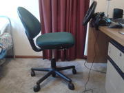
Much better height
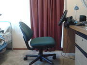
Then I calculated the total space taking into account thickness of steel and wood sheeting. So a 230mm total height pivot. Allowing for steel and mdf to make up height of frame.
I used steel I had around and mdf sheet. But for reference. 16mm mdf, 25mm steel for top and 12mm mdf and 30mm steel for bottom.
As long as you allow for a total measurement with materials, you can get the overall height needed .
The top frame was the same size as the seat. 430 x 400
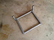
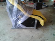
I welded some up supports for the motors to connect to so it overcomes centre of gravity as motors are mounted at the front.
You can see a trial fitting of the seat before I fixed the mdf sheet down.
Base is 550 x 610, 30mm steel and 12mm plywood because thats what I had in steel lying around. And I need to fit psu, jrks, motors.
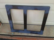
Heres a shot of the base with cut down brackets for the motors to mount to
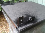
The pivot is a cut to size tailshaft end.
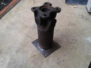
I welded a plate on the end and drilled holes for bolts to mount to it.
And painted it
Pivot is 230mm total height
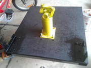
Pivot is at best point of balance
Motor lever arms are 40mm centre to centre steel with 12mm hole for motor bolt and 10mm hole for rod end.

Once all frames were done, I sat the top frame on set it to a level I wanted, then I measured the distance between arms and top of frame connecting points, taking into account rod end lengths and nuts on the threaded rod.
I made some rod arms up with 180mm lengths of 20mm box steel and welded threaded rod into the ends
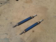
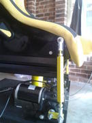
The pots were mounted with a hole in the centre of the motor bolt shaft , then I measured up the bracket to drill the hole in the bracket to mount the pot to. The pot shaft was fitted into the back of the motor bolt and I drilled a 2mm hole right though the bolt and pot, I fitted a length of wire through it, twisted the wire to hold it and araldite glues the pot shaft for good measure.
You can see in this photo of the pots mounted.
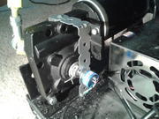
Then it was a matter of wiring jrks, power supplies, wiring motors, and bolting it all together.
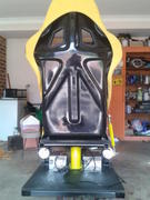
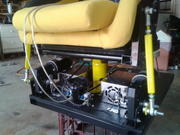
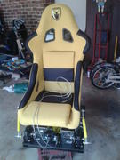
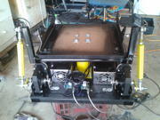
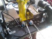
and finally at the desk inside the house
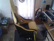
Its so compact I can fit it in my walk in wardrobe as well when its not in use
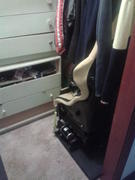
Cheers, David.
Heres some videos
and to show it does make fine road vibration, I taped my phone to the side of the seat.
Heres the website it also lives on
xsimulator.net/community/thr … 2dof.5326/

