I have a question about a way to use the 23201a serial adapter. I’m thinking I’m trying to use it in a way that it is not intended. I looked at the datasheet for the TI MA3238C but it wasn’t apparent to me if I’m still thinking about this wrong. I bought one of these back in 2010 so it’s likely not the updated design with the LC protection which makes me more wary to test various things.
Basically what I need is a TTL to RS232 converter and was hoping to use this unused 23201a.
What I’m trying to do is connect an external TTL TX/RX device(a bluetooth radio) to an existing embedded uC product that already has a MAX232 chip on the PCB which allows RS232 communications through a DB9 connector on the case. I’m just trying to get wireless serial comms to the existing product. The radio needs 3.6-6V power supply but 3.3V level TX and RX communications. Can I connect the 23201a to the radio and then just connect the two DB9 connectors together and expect it to work? The PCB with the DB9 and MAX232 puts gnd and +5V out on the connector along with the RS232 TX and RX pins which is all I would need. Does the 23201a pass that 5 volt on through somewhere to power the radio? Are the RX(pin 2) TX(pin 3) on the 23201a at 3.3V levels? Is the VCC (pin 10) at 3.3 or 5V?
I’m just a bit confused at the function of this product.
Our 23201 serial adapter can be used to convert RS-232 signals from a DB9 connector to logic level signals with voltages between 3V to 5.5V.
I am not sure exactly what you mean by the PCB putting +5V out on the connector, but if your device applies 5V to one of the adapter’s outputs it could damage the adapter.
It is hard to answer this question, since you did not specify which pin on the connector you are referring to. However, please note that the VCC pin is a logic supply input for the adapter. The DB9 connector on the adapter does not directly transfer the voltage supplied to VCC, and probably cannot be used to power your radio.
If you are not sure which version you have, you can add your own capacitor across VCC and GND. (Around 100uF should be fine).
In addition, not all serial devices can be connected with the same type of cable; you should carefully examine the pinouts of the devices you are trying to connect to determine whether you need a null modem cable or not.
In general, your questions are hard to answer because they are phrased as questions about your proposed overall system, and we are unfamiliar with many of the components in your system. It is good to give us some context, but please try to phrase your questions so that they are about the behavior of our products.
Let me try and break it down more objectivly instead of rambling on vaugly about what I have and what I wonder might work.
I have a system which uses the Motorola MC68HC908GP32 microprocessor. For a serial communication interface it has a pair of Tx and Rx pins.
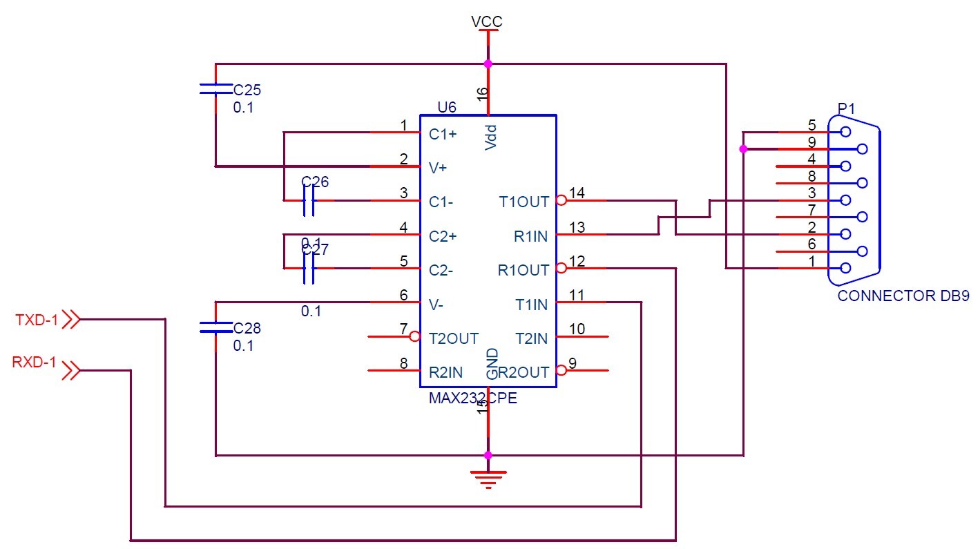
These pins are routed to an on-board(same PCB) circuit utilizing a MAX232CPE IC. The serial comms are then routed to a PCB mounted DB-9 connector which can be directly connected to a PC’s serial port for accessing program variables or for flashing the microprocessor.
I picked up an inexpensive bluetooth adapter which has a 4-pin header connector. It needs +5VDC and Ground(2 of the 4 pins) for power and has a Tx and Rx line(the last 2 pins) which is at TTL/3.3V level for serial communications. I want to use this adapter to add wireless serial communications to my system.
My preference would be to add a circuit to the bluetooth module such that I can directly connect it to the DB9 connector on the system and not remove any current internal system circuitry so that I could then unplug it and connect a PC if needed in the future without making internal modifications. Would the 23201a work as this circuit to allow this type of integration?
What I did just last night, and it did work, was desolder the MAX232 IC and replace it with a 16 pin IC socket which then gave me direct access to the +5V, gnd, and microprocessor Tx and Rx lines. I connected these to the appropriate pins on the bluetooth module(micro-Tx → BT-Rx, and micro Rx → BT-Tx) and was able to access the microprocessor wirelessly w/ an Android based tablet. Because I used a socket I can always put the MAX232 IC back in for standard serial port operation. But I’d still like the system more adaptable without needing to open the case to swap that IC in and out.
Below are some datahsheets and attached is a snipit of the schematic on how the MAX232 is integrated. My idea is if I can convert the RS232 level serial lines to TTL then I can connect those through DB9 pins 2 and 3, then just use pins 1 and 5/9 for +5V and ground to power the module.
Assuming that you use an appropriate cable type that connects pin 1 on the DB9 connector of your existing system to pin 1 (or one of the other input pins) on the DB9 connector of the serial adapter, I think the setup you proposed should work. However, you will probably need to solder a jumper onto the DB9 connector on the adapter to access the 5V output and then use a regulator to step it down to 3.3V to power the adapter.