My name is Jean, new to this forum, and I have some porblems with my 2 channel 12v relay carrier #2487.
I have made a circuit, where an 11 to 14vdc car battery supply is feeded into a 12v step up/down regulator ( S13V25F12) which powers the relay carrier (and a few other parts).
From an old circuitboard (old 12v radio) there are two signals going to the EN1 and EN2 of the relay carrier.
EN1 is an 8Vdc very low current signal coming from an 16pin IC. 0.1Vdc is OFF signal and 8Vdc is ON signal.
EN2 is an low current 11.5Vdc signal coming from another IC via a series of mechanical switches.
The entire setup works perfectly, until today the relay carrier was non responsive.
The LED of EN1 was very dimly lit, and EN1 was pulling too much current, making the voltage drop to 0.4Vdc.
EN2 did not respond anymore.
Pulling all the wiring, and using a 12v lab power supply only on GND and VCC, the EN1 led was still lit very dim. After applying 12v on EN1, the relay switched, and the led was bright. Removing the 12v on EN1 keeps the Led and relay switched on. Powercycling the board has no effect. EN1 stays lit and switched without any supply tot the EN pin, and EN2 is still not responsive.
It seems that both channel opamps died, but can anyone tell me why, or is it bad luck?
The radio is 12v carbattery fed, so a higher voltage of 14v seems unlikely. The datasheet states that EN1&EN2 can accept upto 20Vdc.
Unfortunately, electronics like this can be damaged in a variety of ways, many of which are difficult to identify after the fact. Stray voltages and electrostatic discharge (ESD) are a couple examples. That makes it hard to know for sure what might have happened to your board, but if you can post some pictures of your setup that show all of your connections, I can let you know if anything stands out.
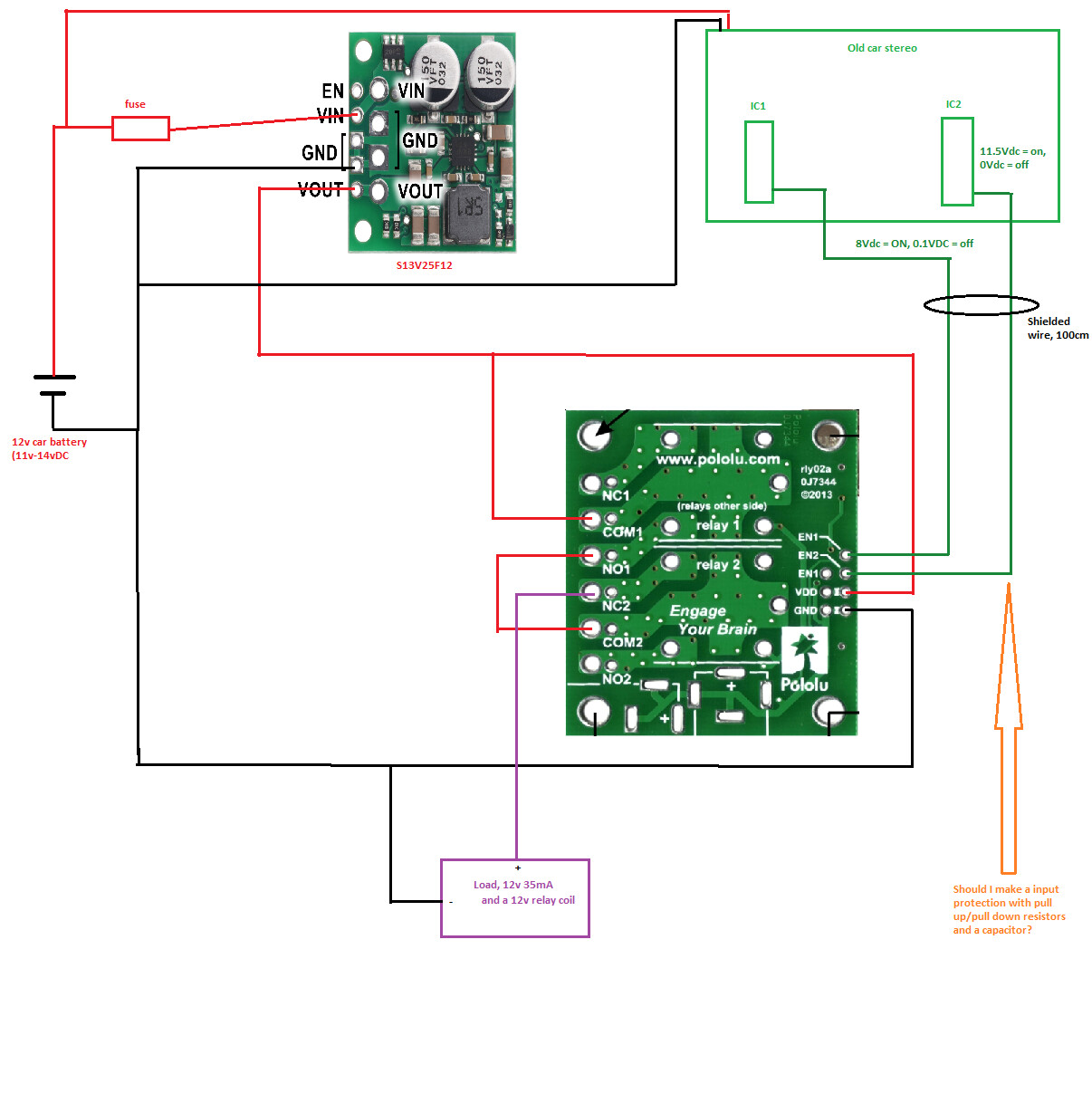
This is in short what I made. IC1 and IC2 are existing IC’s in a radio, and I want to ‘catch’ their state. I connected a wire to a existing pin, which switches accordingly to the function I want to catch. The IC pin is 8vdc for IC1 for ON state, and 11.5vdc for IC2 for ON state. The Off state is 0vdc. The IC is so old (40years), no datasheet is available.
The function: when IC1 is “on” and IC2 is “off” then the load needs to be powered up. If both IC’s are “on”, or only IC2 is on, then the load needs to be off.
Should I make a protection circuit with a resistor in series with the green wire, and maybe a pull up/down resistor and bypass capacitor also, to prevent spikes?
Could you help me with a setup? I can’t draw too much current from the IC’s, because it still switches it’s original circuit.
It seems like your setup is putting three relays in series. I am not sure what the effect of that is supposed to be, but nothing in the connection diagram you posted stands out as being particularly problematic.
As long as the activation time for the relay is not too critical, adding a resistor in series with each of your signals seems like an easy way to add some protection. It is hard for me to comment on the necessity of that or possibility of inadvertent consequences though since it is a system level design question that depends on having more knowledge about the ICs generating the signals.
Ultimately, if you cannot find more information about the ICs, then the safest way to proceed would be to monitor your setup with an oscilloscope so you can see what is really going on.
A capacitor might help in case there is a spike on the EN signals, but as I mentioned before, I cannot advise on the likelihood of that being the problem since we do not have much information about the signals to go off of.
Since you mentioned using a car battery, another thing to keep in mind is the power in automotive environments can be very noisy. I would typically expect the relay carrier to be okay since it is being powered through the regulator, but you might want to take steps to avoid exposing the regulator to high transients. You can look at documents such as this Littelfuse application note for information about that
Since the signals you are connecting to EN are supposed to be 8V and 11.5V, why not choose a diode with a clamping voltage above those, but below the relay carrier’s 20V max?
Otherwise, your plan seems okay. Like I mentioned before though, the safest way to proceed would be to monitor your setup with an oscilloscope so you can see what is really going on.