1.8" TFT Display to Baby-O with Arduino code

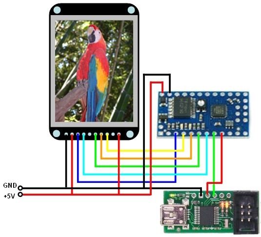
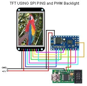
Tonight I did a successful interface to a 1.8" TFT display to the Baby-O using the Arduino code provided from the ladyada.net website. http://www.ladyada.net/products/18tftbreakout/

I used a modified version of the Pololu method for programming Orangatangs using the Arduino Environment https://www.pololu.com/docs/0J17 and a modified version of the ladyada Arduino sketch.

I also used the Baby-O serial Tx/Rx pins, PD0/PD1 wired to the Pololu USB AVR Programmer Tx/Rx pins to send text back to my laptop at the end of the main graphic examples for debug info. The serial port was already setup in the Arduino sketch, so I decided to put it to use (9600/8/N/1). (Note: The USB AVR Programmer sets up 2 COM ports. One is used for programming, the other is a TTL port which uses the Tx/Rx pins.)

The sketch code is posted below. I had to use the “File–>Upload Using Programmer” menu option to get the USB AVR Programmer to work. There is another sketch which shows you how to rotate graphics and text on the display. There is a slight learning curve for the display, but you should be able to figure out what is happening from the sketch code and experimentation.

Keep Having Fun.

Charlie D

// Setup for Pololu BabyO328P
// Serial from BabyO has to be wired to the Pololu USB Programmer
// On the Arduino, PDO/PD1 is wired to the ATMEGA16U PD3(Tx)/PD2(Rx)
// Serial Pins 328P Rx/Tx = 30/31 PD0/PD1 (BabyO Header 8/9)
// Wire BabyO 8/9 to Pololu USB Programmer Tx/Rx on header
// Note: Tx(9) gets wired to Rx and Rx(8) to Tx as a NULL MODEM
// Grounds should be connected as well

// You can use any (4 or) 5 pins 
// The BabyO uses PD5 and PB3 for Motor Control so I wanted to avoid these
// Since we can use any pins, I decided on PB1, PB2, PB4, PB5

                  //                 Arduino          328P  BabyO
#define sclk 9    // for BabyO328 use pin 09 Mapped to PB1 (Header 04)
#define mosi 10   // for BabyO328 use pin 10 Mapped to PB2 (Header 05)
#define cs 12     // for BabyO328 use pin 12 Mapped to PB4 (Header 06)
#define dc 13     // for BabyO328 use pin 13 Mapped to PB5 (Header 07)
#define rst 8     // for BabyO328 use pin 08 Mapped to PB0 (Header 03)

// Color definitions
#define	BLACK           0x0000
#define	BLUE            0x001F
#define	RED             0xF800
#define	GREEN           0x07E0
#define CYAN            0x07FF
#define MAGENTA         0xF81F
#define YELLOW          0xFFE0  
#define WHITE           0xFFFF

#include <ST7735.h>
// Not sure how the SPI.h is used in the Option 1 (slow method)
// Need to study how SPI is emulated for any pins
#include <SPI.h>

// Option 1: use any pins but a little slower
ST7735 tft = ST7735(cs, dc, mosi, sclk, rst);  

// Option 2: must use the hardware SPI pins 
// (for UNO thats sclk = 13 and sid = 11) and pin 10 must be 
// an output. This is much faster - also required if you want
// to use the microSD card (see the image drawing example)
//ST7735 tft = ST7735(cs, dc, rst);    
float p = 3.1415926;

void fillpixelbypixel(uint16_t color) {
  for (uint8_t x=0; x < tft.width(); x++) {
    for (uint8_t y=0; y < tft.height(); y++) {
      tft.drawPixel(x, y, color);
    }
  }
  delay(100);
}

void setup(void) {
  Serial.begin(9600);
  Serial.print("Hello!  ");
  tft.initR();               // initialize a ST7735R chip

  Serial.print("Init Start.  ");
  tft.writecommand(ST7735_DISPON);
  
  uint16_t time = millis();
  tft.fillScreen(BLACK);
  time = millis() - time;
  
  Serial.print("Init Complete.  ");
  Serial.print("Run Time: ");
  Serial.println(time, DEC);
  delay(500);
  
  //
  tft.fillScreen(BLACK);
  testdrawtext("Lorem ipsum dolor sit amet, consectetur adipiscing elit. Curabitur adipiscing ante sed nibh tincidunt feugiat. Maecenas enim massa, fringilla sed malesuada et, malesuada sit amet turpis. Sed porttitor neque ut ante pretium vitae malesuada nunc bibendum. Nullam aliquet ultrices massa eu hendrerit. Ut sed nisi lorem. In vestibulum purus a tortor imperdiet posuere. ", WHITE);
  delay(1000);
  // time = millis() - time;
  Serial.print("End DrawText Display. ");
  
  // tft print function!
  tftPrintTest();
  delay(4000);
  Serial.print("End PrintTest. ");
  
  //a single pixel
  tft.drawPixel(tft.width()/2, tft.height()/2, GREEN);
  delay(500);
  Serial.print("End DrawPixel. ");
  
  // line draw test
  testlines(YELLOW);
  delay(500);
  Serial.print("End testlines Yellow. ");  
  
  // optimized lines
  testfastlines(RED, BLUE);
  delay(500);    
  Serial.print("End testFastLines Red Blue. ");

  testdrawrects(GREEN);
  delay(500);
  Serial.print("End testDrawRects Green. ");

  testfillrects(YELLOW, MAGENTA);
  delay(500);
  Serial.print("End testFillRects Yellow Magenta. ");

  tft.fillScreen(BLACK);
  testfillcircles(10, BLUE);
  testdrawcircles(10, WHITE);
  Serial.print("End testCircles. ");
  
  testroundrects();
  delay(500);
  Serial.print("End testRoundRects. ");
  
  testtriangles();
  delay(500);
  Serial.print("End testTriangles. ");
  
  mediabuttons();
  delay(500);
  Serial.print("End mediaButtons. ");
  
  Serial.print("Done. ");
  delay(1000);
}

void loop() {
  tft.writecommand(ST7735_INVON);
  delay(500);
  tft.writecommand(ST7735_INVOFF);
  delay(500);
}

void testlines(uint16_t color) {
   tft.fillScreen(BLACK);
   for (uint16_t x=0; x < tft.width(); x+=6) {
     tft.drawLine(0, 0, x, tft.height()-1, color);
   }
   for (uint16_t y=0; y < tft.height(); y+=6) {
     tft.drawLine(0, 0, tft.width()-1, y, color);
   }
   
   tft.fillScreen(BLACK);
   for (uint16_t x=0; x < tft.width(); x+=6) {
     tft.drawLine(tft.width()-1, 0, x, tft.height()-1, color);
   }
   for (uint16_t y=0; y < tft.height(); y+=6) {
     tft.drawLine(tft.width()-1, 0, 0, y, color);
   }
   
   tft.fillScreen(BLACK);
   for (uint16_t x=0; x < tft.width(); x+=6) {
     tft.drawLine(0, tft.height()-1, x, 0, color);
   }
   for (uint16_t y=0; y < tft.height(); y+=6) {
     tft.drawLine(0, tft.height()-1, tft.width()-1, y, color);
   }

   tft.fillScreen(BLACK);
   for (uint16_t x=0; x < tft.width(); x+=6) {
     tft.drawLine(tft.width()-1, tft.height()-1, x, 0, color);
   }
   for (uint16_t y=0; y < tft.height(); y+=6) {
     tft.drawLine(tft.width()-1, tft.height()-1, 0, y, color);
   }
   
}

void testdrawtext(char *text, uint16_t color) {
  tft.drawString(0, 0, text, color);
}

void testfastlines(uint16_t color1, uint16_t color2) {
   tft.fillScreen(BLACK);
   for (uint16_t y=0; y < tft.height(); y+=5) {
     tft.drawHorizontalLine(0, y, tft.width(), color1);
   }
   for (uint16_t x=0; x < tft.width(); x+=5) {
     tft.drawVerticalLine(x, 0, tft.height(), color2);
   }
}

void testdrawrects(uint16_t color) {
 tft.fillScreen(BLACK);
 for (uint16_t x=0; x < tft.width(); x+=6) {
   tft.drawRect(tft.width()/2 -x/2, tft.height()/2 -x/2 , x, x, color);
 }
}

void testfillrects(uint16_t color1, uint16_t color2) {
 tft.fillScreen(BLACK);
 for (uint16_t x=tft.width()-1; x > 6; x-=6) {
   tft.fillRect(tft.width()/2 -x/2, tft.height()/2 -x/2 , x, x, color1);
   tft.drawRect(tft.width()/2 -x/2, tft.height()/2 -x/2 , x, x, color2);
 }
}

void testfillcircles(uint8_t radius, uint16_t color) {
  for (uint8_t x=radius; x < tft.width(); x+=radius*2) {
    for (uint8_t y=radius; y < tft.height(); y+=radius*2) {
      tft.fillCircle(x, y, radius, color);
    }
  }  
}

void testdrawcircles(uint8_t radius, uint16_t color) {
  for (uint8_t x=0; x < tft.width()+radius; x+=radius*2) {
    for (uint8_t y=0; y < tft.height()+radius; y+=radius*2) {
      tft.drawCircle(x, y, radius, color);
    }
  }  
}

void testtriangles() {
  tft.fillScreen(BLACK);
  int color = 0xF800;
  int t;
  int w = 63;
  int x = 159;
  int y = 0;
  int z = 127;
  for(t = 0 ; t <= 15; t+=1) {
    tft.drawTriangle(w, y, y, x, z, x, color);
    x-=4;
    y+=4;
    z-=4;
    color+=100;
  }
}

void testroundrects() {
  tft.fillScreen(BLACK);
  int color = 100;
  int i;
  int t;
  for(t = 0 ; t <= 4; t+=1) {
  int x = 0;
  int y = 0;
  int w = 127;
  int h = 159;
    for(i = 0 ; i <= 24; i+=1) {
    tft.drawRoundRect(x, y, w, h, 5, color);
    x+=2;
    y+=3;
    w-=4;
    h-=6;
    color+=1100;
  }
  color+=100;
  }
}

void tftPrintTest() {
  tft.fillScreen(BLACK);
  tft.setCursor(0, 30);
  tft.setTextColor(RED);  
  tft.setTextSize(1);
  tft.println("Hello World!");
  tft.setTextColor(YELLOW);
  tft.setTextSize(2);
  tft.println("Hello World!");
  tft.setTextColor(GREEN);
  tft.setTextSize(3);
  tft.println("Hello World!");
  tft.setTextColor(BLUE);
  tft.setTextSize(4);
  tft.print(1234.567);
  delay(1500);
  tft.goHome(); // go to 0, 0
  tft.fillScreen(BLACK);
  tft.setTextColor(WHITE);
  tft.setTextSize(0);
  tft.println("Hello World!");
  tft.setTextSize(1);
  tft.setTextColor(GREEN);
  tft.print(p, 6);
  tft.println(" Want pi?");
  tft.println(" ");
  tft.print(8675309, HEX); // print 8,675,309 out in HEX!
  tft.println(" Print HEX!");
  tft.println(" ");
  tft.setTextColor(WHITE);
  tft.println("Sketch has been");
  tft.println("running for: ");
  tft.setTextColor(MAGENTA);
  tft.print(millis() / 1000);
  tft.setTextColor(WHITE);
  tft.print(" seconds.");
}

void mediabuttons() {
 // play
  tft.fillScreen(BLACK);
  tft.fillRoundRect(25, 10, 78, 60, 8, WHITE);
  tft.fillTriangle(42, 20, 42, 60, 90, 40, RED);
  delay(500);
  // pause
  tft.fillRoundRect(25, 90, 78, 60, 8, WHITE);
  tft.fillRoundRect(39, 98, 20, 45, 5, GREEN);
  tft.fillRoundRect(69, 98, 20, 45, 5, GREEN);
  delay(500);
  // play color
  tft.fillTriangle(42, 20, 42, 60, 90, 40, BLUE);
  delay(50);
  // pause color
  tft.fillRoundRect(39, 98, 20, 45, 5, RED);
  tft.fillRoundRect(69, 98, 20, 45, 5, RED);
  // play color
  tft.fillTriangle(42, 20, 42, 60, 90, 40, GREEN);
}

Here is the wiring diagram.


I have been playing with my display and came across a problem when the screen is rotated. The normal screen width is 128 the the height is 160 for rotation 0. If you rotate the screen using setRotation(1), the orientation changes to 160x128 instead of 128x160. When I tried to display text past 128 pixels or draw circles that went past 128 in the x direction, they would not draw. I found the error to be in the ST7735 Library File: ST7735.cpp. The function, drawPixel(); was doing a check for x > 128 || y > 160. If either was found to be TRUE, the function did an immediate return.

void ST7735::drawPixel(uint8_t x, uint8_t y,uint16_t color) {
  if ((x >= TFTWIDTH) || (y >= TFTHEIGHT)) return;
    
    // check rotation, move pixel around if necessary
  switch (rotation) {
  case 1:
    swap(x, y);
    x = TFTWIDTH - x - 1;
    break;
  case 2:
    x = TFTWIDTH - x - 1;
    y = TFTHEIGHT - y - 1;
    break;
  case 3:
    swap(x, y);
    y = TFTHEIGHT - y - 1;
    break;
  }
  
  setAddrWindow(x,y,x+1,y+1);
  
  // setup for data
  *portOutputRegister(rsport) |= rspin;
  *portOutputRegister(csport) &= ~ cspin;
  
  spiwrite(color >> 8);    
  spiwrite(color);   
  
  *portOutputRegister(csport) |= cspin;
  
}


void ST7735::fillScreen(uint16_t color) {
  setAddrWindow(0, 0, TFTWIDTH-1, TFTHEIGHT-1);
  
  // setup for data
  *portOutputRegister(rsport) |= rspin;
  *portOutputRegister(csport) &= ~ cspin;
  
  for (uint8_t x=0; x < TFTWIDTH; x++) {
    for (uint8_t y=0; y < TFTHEIGHT; y++) {
      spiwrite(color >> 8);    
      spiwrite(color);    
    }
  }
  
  *portOutputRegister(csport) |= cspin;
}

I commented out the line: if ((x >= TFTWIDTH) || (y >= TFTHEIGHT)) return; This fixed the problem for both text and drawCircle(); The real fix would be to do a test for the rotation value and then test for x, y values.

Best Regards,
charlie

I have some new code for displaying some of the Baby-O ports on the display.

I display ADC5/6/7 using the ADC value and a bar graph. ADC7 is connected to the on board Potentiometer. I wired ADC6 to a IR detector circuit and ADC5 to an external potentiometer.

I display Port D pins using simulated green LEDs. I know that PD3/5/6 are not available as they are wired to the H-Bridge, but I’m only testing for PD0/1/2/4/7 in the code. PD0 is always on in my hook up because it is wired to the serial port. You can test the other Port D pins using a 10k Ohm resistor wired to Vcc.

Other parts of the display are testing the problem with text and circles, which use the drawpixel(); function.

Keep having fun,
charlie

/*
 AnalogReadTFT Routines
 Reads an analog input on pin 0, prints the result to a TFT Graphic Display 
 DigiatalPortRead Routines
 Reads a BYTE from the serial port and displays it as Simulated Red LEDs
*/

// Setup for Pololu BabyO328P
// Serial from BabyO has to be wired to the Pololu USB Programmer
// On the Arduino, PDO/PD1 is wired to the ATMEGA16U PD3(Tx)/PD2(Rx)
// Serial Pins 328P Rx/Tx = 30/31 PD0/PD1 (BabyO Header 8/9)
// Wire BabyO 8/9 to Pololu USB Programmer Tx/Rx on header
// Note: Tx(9) gets wired to Rx and Rx(8) to Tx as a NULL MODEM
// Grounds should be connected as well

// You can use any (4 or) 5 pins 
// The BabyO uses PD5 and PB3 for Motor Control so I wanted to avoid these
// Since we can use any pins, I decided on PB1, PB2, PB4, PB5

                  //                 Arduino          328P  BabyO
#define sclk 9    // for BabyO328 use pin 09 Mapped to PB1 (Header 04)
#define mosi 10   // for BabyO328 use pin 10 Mapped to PB2 (Header 05)
#define cs 12     // for BabyO328 use pin 12 Mapped to PB4 (Header 06)
#define dc 13     // for BabyO328 use pin 13 Mapped to PB5 (Header 07)
#define rst 8     // for BabyO328 use pin 08 Mapped to PB0 (Header 03)

// Color definitions
#define	BLACK           0x0000
#define	BLUE            0x001F
#define	RED             0xF800
#define	GREEN           0x07E0
#define CYAN            0x07FF
#define MAGENTA         0xF81F
#define YELLOW          0xFFE0  
#define WHITE           0xFFFF

#include <ST7735.h>
#include <SPI.h>

// Option 1: use any pins but a little slower
ST7735 tft = ST7735(cs, dc, mosi, sclk, rst);

int sensorValueNew = 0;
int sensorValue5 = 0;  
int sensorValue6 = 0;
int sensorValue7 = 0;
int sensor = 0;
int xFill = 0;

int Pin0 = 0;
int Pin1 = 1;
int Pin2 = 2;
int Pin4 = 4;
int Pin7 = 7;
// the following pins not available on Baby-O
int Pin3 = 3;
int Pin5 = 5;
int Pin6 = 6;

String sensorString = "0000";

void setup() {
  // Serial.begin(9600);	    // Open the COM port
  tft.initR();			    // initialize a ST7735R chip
  tft.writecommand(ST7735_DISPON);
  mainScreen();
  babyPortDSetup();
  testCircles();
}

void loop() {
  updateSensor(5);
  updateSensor(6);
  updateSensor(7);
  babyPortDLED(0);
  babyPortDLED(1);
  babyPortDLED(2);
  babyPortDLED(4);
  babyPortDLED(7);
  delay(100);
}

void updateSensor (uint8_t sensor) {
  switch (sensor) {
    case 5:
      sensorValueNew = analogRead(A5);
      if (sensorValueNew == sensorValue5)
      {
        break;
      }
      else
      {
        tft.setTextColor(BLUE);
        tft.setCursor(2,2);
        tft.println("ADC5: ");
        tft.fillRect(30, 2, 25, 8, WHITE);
        // Serial.print("ADC5: ");
        // Serial.print(sensorValueNew);
        // Serial.print(", ");
        tft.setTextColor(RED);
        sensorString = String(sensorValueNew);
        int x = sensorString.length();
        padSensor(x);

        tft.setCursor(31,2);
        tft.print(sensorString);
        xFill = (sensorValueNew / 10);
        if (xFill > 100){
          xFill = 100;
        }
        tft.fillRect(58, 2, xFill, 8, GREEN);
        tft.fillRect(58+xFill+1, 2, 100-xFill-1, 8, WHITE);
        sensorValue5 = sensorValueNew;
        break;
      }
    
    case 6:
    sensorValueNew = analogRead(A6);
      if (sensorValueNew == sensorValue6)
      {
        break;
      }
      else
      {
        tft.setTextColor(BLUE);
        tft.setCursor(2,13);
        tft.println("ADC6: ");
        tft.fillRect(30, 13, 25, 8, WHITE);
        // Serial.print("ADC6: ");
        // Serial.print(sensorValueNew);
        // Serial.print(", ");
        tft.setTextColor(RED);
        sensorString = String(sensorValueNew);
        int x = sensorString.length();
        padSensor(x);
        tft.setCursor(31,13);
        tft.print(sensorString);
        xFill = (sensorValueNew / 10);
        if (xFill > 100){
          xFill = 100;
        }
        tft.fillRect(58, 13, xFill, 8, CYAN);
        tft.fillRect(58+xFill+1, 13, 100-xFill-1, 8, WHITE);
        sensorValue6 = sensorValueNew;
        break;
      }
    
    case 7:
    sensorValueNew = analogRead(A7);
      if (sensorValueNew == sensorValue7)
      {
        break;
      }
      else
      {
        tft.setTextColor(BLUE);
        tft.setCursor(2,25);
        tft.println("ADC7: ");
        tft.fillRect(30, 25, 25, 8, WHITE);
        // Serial.print("ADC7: ");
        // Serial.print(sensorValueNew);
        // Serial.print(", ");
        tft.setTextColor(RED);
        sensorString = String(sensorValueNew);
        int x = sensorString.length();
        padSensor(x);
        tft.setCursor(31,25);
        tft.print(sensorString);
        xFill = (sensorValueNew / 10);
        if (xFill > 100){
          xFill = 100;
        }
        tft.fillRect(58, 24, xFill, 8, YELLOW);
        tft.fillRect(58+xFill+1, 24, 100-xFill-1, 8, WHITE);
        sensorValue7 = sensorValueNew;
        break;
      }
    
    default:
    // Error should not be here.
    break;
  }
}

void padSensor (uint8_t xLen){
 switch (xLen){
   case 1:
     sensorString = "000" + sensorString;
   break;
          
   case 2:
     sensorString = "00" + sensorString;
   break;
          
   case 3:
     sensorString = "0" + sensorString;
   break;
          
   case 4:
   break;
          
   default:
     sensorString = "Err";
   break;
  } 
}

void mainScreen (void) {
  tft.setRotation(1);
  tft.setTextSize(1);
  tft.fillScreen(WHITE);
  tft.drawRect(57, 1, 102, 10, BLACK);
  tft.drawRect(57, 12, 102, 10, BLACK);
  tft.drawRect(57, 23, 102, 10, BLACK);
  tft.drawHorizontalLine(58, 36, 102, BLACK);
  tft.drawVerticalLine(58, 34, 5, BLACK);
  tft.drawVerticalLine(68, 34, 5, BLACK);
  tft.drawVerticalLine(78, 34, 5, BLACK);
  tft.drawVerticalLine(88, 34, 5, BLACK);
  tft.drawVerticalLine(98, 34, 5, BLACK);
  tft.drawVerticalLine(108, 34, 5, BLACK);
  tft.drawVerticalLine(118, 34, 5, BLACK);
  tft.drawVerticalLine(128, 34, 5, BLACK);
  tft.drawVerticalLine(138, 34, 5, BLACK);
  tft.drawVerticalLine(148, 34, 5, BLACK);
  tft.drawVerticalLine(158, 34, 5, BLACK);
  tft.setTextColor(BLACK);
  tft.setCursor(56,39);
  tft.print("0");
  tft.setCursor(72,39);
  tft.print("20");
  tft.setCursor(93,39);
  tft.print("40");
  tft.setCursor(113,39);
  tft.print("60");
  tft.setCursor(133,39);
  tft.print("80");
  // tft.setCursor(145,39);
  // tft.print("100");
  testdrawtext("012345678901234567890123456789012", BLUE);
}

void babyPortDLED (uint8_t LED){
  int stateLED;
  
  switch (LED){

    case 0:
    stateLED = digitalRead(Pin0);
    if (stateLED == 0){
      tft.fillCircle(123, 60, 4, BLACK);
    }
    else {
      tft.fillCircle(123, 60, 4, GREEN);
      tft.drawCircle(123, 60, 4, BLACK);
    }
    break;
    
    case 1:
    stateLED = digitalRead(Pin1);
    if (stateLED == 0){
      tft.fillCircle(113, 60, 4, BLACK);
    }
    else {
      tft.fillCircle(113, 60, 4, GREEN);
      tft.drawCircle(113, 60, 4, BLACK);
    }
    break;
    
    case 2:
    stateLED = digitalRead(Pin2);
    if (stateLED == 0){
      tft.fillCircle(103, 60, 4, BLACK);
    }
    else {
      tft.fillCircle(103, 60, 4, GREEN);
      tft.drawCircle(103, 60, 4, BLACK);
    }
    break;
    
    case 3:
    stateLED = digitalRead(Pin3);
    if (stateLED == 0){
      tft.fillCircle(93, 60, 4, BLACK);
    }
    else {
      tft.fillCircle(93, 60, 4, GREEN);
      tft.drawCircle(93, 60, 4, BLACK);
    }
    break;
    
    case 4:
    stateLED = digitalRead(Pin4);
    if (stateLED == 0){
      tft.fillCircle(83, 60, 4, BLACK);
    }
    else {
      tft.fillCircle(83, 60, 4, GREEN);
      tft.drawCircle(83, 60, 4, BLACK);
    }
    break;
    
    case 5:
    stateLED = digitalRead(Pin5);
    if (stateLED == 0){
      tft.fillCircle(73, 60, 4, BLACK);
    }
    else {
      tft.fillCircle(73, 60, 4, GREEN);
      tft.drawCircle(73, 60, 4, BLACK);
    }
    break;
    
    case 6:
    stateLED = digitalRead(Pin6);
    if (stateLED == 0){
      tft.fillCircle(63, 60, 4, BLACK);
    }
    else {
      tft.fillCircle(63, 60, 4, GREEN);
      tft.drawCircle(63, 60, 4, BLACK);
    }
    break;
    
    case 7:
    stateLED = digitalRead(Pin7);
    if (stateLED == 0){
      tft.fillCircle(53, 60, 4, BLACK);
    }
    else {
      tft.fillCircle(53, 60, 4, GREEN);
      tft.drawCircle(53, 60, 4, BLACK);
    }
    break;
    
    default:
    break;
  }
}

void babyPortDSetup (void){
  tft.drawRoundRect(2, 54, 154, 21, 3, RED);
  tft.drawRect(0, 52, 158, 25, RED);
  tft.fillCircle(53, 60, 4, BLACK);
  tft.fillCircle(63, 60, 4, BLACK);
  tft.fillCircle(73, 60, 4, BLACK);
  tft.fillCircle(83, 60, 4, BLACK);
  tft.fillCircle(93, 60, 4, BLACK);
  tft.fillCircle(103, 60, 4, BLACK);
  tft.fillCircle(113, 60, 4, BLACK);
  tft.fillCircle(123, 60, 4, BLACK);
  pinMode(Pin0, INPUT);
  pinMode(Pin1, INPUT);
  pinMode(Pin2, INPUT);
  pinMode(Pin4, INPUT);
  pinMode(Pin7, INPUT);
  tft.setTextColor(BLACK);
  tft.setCursor(5, 57);
  tft.print("PORT:D");
  tft.setCursor(50, 66);
  tft.print("7");
  tft.setCursor(61, 66);
  tft.print("6");
  tft.setCursor(71, 66);
  tft.print("5");
  tft.setCursor(81, 66);
  tft.print("4");
  tft.setCursor(91, 66);
  tft.print("3");
  tft.setCursor(101, 66);
  tft.print("2");
  tft.setCursor(111, 66);
  tft.print("1");
  tft.setCursor(121, 66);
  tft.print("0");
}

void testdrawtext(char *text, uint16_t color) {
  tft.drawString(0, 80, text, color);
}

void testCircles(void){
 for (int z = 1; z < 21; z++){
   tft.fillCircle((z * 8)-4, 105, 4, RED);
   tft.drawCircle((z * 8)-4, 115, 4, BLACK);
 }
}

Hi, Charlie.

Thanks for sharing your project and code! I would love to see pictures or videos.

- Ryan

Ryan,

I’ll see what I can do tonight. The screen is so bright, that I wasn’t able to take pictures. I’ll try to dim the back light with PWM or change the screen colors to take some photos.

I’ve been woring on some other BMPs, other display screens and a compass dial screen to hook up to my ACCEL/compass module. I’ll post the code when I get done testing.

I’m not sure how to post videos. I was concerned about wasting server space on the forum.

Best regards,

charlie

A lot of people post the video on YouTube and then post a link.

- Ryan

Here is a couple of screens I designed for the display.

Notice the breadboard layout. I’m using pin 4 (PB3) from the ISP header for SPI mode.


A couple of videos showing the display running:

http://www.youtube.com/watch?v=bJL3H3qyT1U

http://www.youtube.com/watch?v=fiQjDeQi_T0

Keep having fun…

Charlie

Here is the wiring for the SPI Mode:

Here is the Arduino code for the Dial display. This is a work in progress, but you can see how I draw the display and set the needle using sin(). There are comments on how to move and resize the dial. The code below is using SPI mode, so I’m not able to drive one of my motors using PB3. PB3 is accessed via the ISP header, pin 4.

The potentiometer on ADC7 is used to change the display bightness.

Keep having fun…
charlie

/*
/*
Creates a Dial and screen to be later used with a GPS
*/

// Setup for Pololu BabyO328P
// Serial from BabyO has to be wired to the Pololu USB Programmer
// On the Arduino, PDO/PD1 is wired to the ATMEGA16U PD3(Tx)/PD2(Rx)
// Serial Pins 328P Rx/Tx = 30/31 PD0/PD1 (BabyO Header 8/9)
// Wire BabyO 8/9 to Pololu USB Programmer Tx/Rx on header
// Note: Tx(9) gets wired to Rx and Rx(8) to Tx as a NULL MODEM
// Grounds should be connected as well

// Pins SCLK and MOSI are fixed in hardware, and pin 10 (or 53) 
// must be an output
// Using Arduino UNO Pins as they are mapped to a ATMEGA328P
// Note: MOSI PB3 is also mapped to Motor Control in the BabyO
// So Motor and SPI Usage are mutually exclusive
// Need to pick up PB3 from the BabyO ISP Header Pin 4
// Use Board: Pololu Orangutan or 3pi robot w/ ATmega328P via Programmer

                  //                 Arduino          328P  BabyO
// #define sclk 13   // for BabyO328 use pin 13 Mapped to PB5 (Header 07)
// #define mosi 11   // for BabyO328 use pin 11 Mapped to PB3 (ISP Header Only)
#define cs 10     // for BabyO328 use pin 10 Mapped to PB2 (Header 05)
#define dc 7      // for BabyO328 use pin 07 Mapped to PD7 (Header 12)
#define rst 8     // for BabyO328 use pin 08 Mapped to PB0 (Header 03)

// Color definitions
#define	BLACK           0x0000
#define	BLUE            0x001F
#define	RED             0xF800
#define	GREEN           0x07E0
#define CYAN            0x07FF
#define MAGENTA         0xF81F
#define YELLOW          0xFFE0  
#define WHITE           0xFFFF
#define DKBLUE          0x0018
#define DKGREEN         0x0600
#define DKRED           0x9802
#define ORANGE          0xF400
#define CREAM           0xFF96
#define BEIGE           0xFF50
#define GREY            0xC618

#include <ST7735.h>
#include <SPI.h>
#include <math.h>

// Option 1: use any pins but a little slower
// ST7735 tft = ST7735(cs, dc, mosi, sclk, rst);

// Option 2: must use the hardware SPI pins 
// (for UNO thats sclk = 13 and sid = 11) and pin 10 must be 
// an output. This is much faster - also required if you want
// to use the microSD card (see the image drawing example)
ST7735 tft = ST7735(cs, dc, rst);

// Let's use the built in POT @ ADC7 to control the backlight
const int backlight = 9;      // Digital Pin 7 PWM for backlight
int brightness = 255;         // PWM for backlight Values 0 - 255
int sensorValueNew = 0;
int sensorValue7 = 0;

// Setting the DialRadius determines the size of the dial.
// int x, y sets the position of the center of the dial.
// All parameters associated with the dial will attempt to
// locate around the dial.  Making the DialRadius too large
// will push parts of text and the dial off the screen.
// Design differnt dials for compass, speed, wind direction, etc.
int DialRadius = 35;
int x = 106;
int y = 64;

// these are used to draw lines and the dial needle
double y_to = 0;
double x_to = 0;
int degree = 0;
double calcSin = 0;
double myPI = 3.14;

// Dummy data to help setup the screen layout
double gpsLat = 0;
double gpsLon = 0;
int gpsSpeed = 30;
int oldgpsSpeed = 0;

// Array used to draw the tick marks around the dial
double tickMarks[12] = {22.5, 45, 67.5, 112.5, 135, 157.5, 202.5, 225, 247.5, 292.5, 315, 337.5};

// Add your Compass data.  Compass data needs to be in degrees.

void setup() {
  // Serial.begin(9600);		// Open the COM port
  tft.initR();			// initialize a ST7735R chip
  tft.writecommand(ST7735_DISPON);
  analogWrite(backlight, brightness);
  tft.setRotation(1);
  tft.setTextSize(1);
  tft.fillScreen(BEIGE);
  tft.fillCircle(x, y, DialRadius+7, CREAM);
  tft.drawCircle(x, y, DialRadius+6, BLACK);
  tft.drawCircle(x, y, DialRadius+3, BLACK);
  tft.fillCircle(x, y, DialRadius+1, CREAM);
  // Current N, S, E, W tick marks.  Will update to triangles later
  tft.drawLine(x, y-DialRadius-10, x, y-DialRadius-1, RED);
  tft.fillCircle(x, y-DialRadius-5, 2, RED);
  // tft.drawLine(x, y+DialRadius+7, x, y+DialRadius+1, RED);
  // tft.drawLine(x-DialRadius-7, y, x-DialRadius-1, y, RED);
  // tft.drawLine(x+DialRadius+7, y, x+DialRadius+1, y, RED);
  // tft.fillTriangle(x-3, y-DialRadius-10, x, y-DialRadius-1, x+3, y-DialRadius-10, RED);
  tft.fillTriangle(x-3, y+DialRadius+10, x+3, y+DialRadius+10, x, y+DialRadius+1, RED);
  tft.fillTriangle(x-DialRadius-10, y-3, x-DialRadius-10, y+3, x-DialRadius-1, y, RED);
  tft.fillTriangle(x+DialRadius+10, y-3, x+DialRadius+10, y+3, x+DialRadius+1, y, RED);
  // the center dot in the middle of the dial
  tft.fillCircle(x, y, 2, BLUE);
  // Text around the dial attempts to adjust to dial size
  tft.setCursor(x-2, y-DialRadius-17);
  tft.setTextColor(RED);
  tft.print("N");
  tft.setCursor(x-2, y+DialRadius+12);
  tft.setTextColor(RED);
  tft.print("S");
  tft.setCursor(x-DialRadius -17, y-3);
  tft.setTextColor(RED);
  tft.print("W");
  tft.setCursor(x+DialRadius+12, y-3);
  tft.setTextColor(RED);
  tft.print("E");
  tft.setCursor((x+((DialRadius+36)/2)), (y-((DialRadius+36)/2)));
  tft.setTextColor(RED);
  tft.print("NE");
  tft.setCursor((x+((DialRadius+30)/2)), (y+((DialRadius+30)/2)));
  tft.setTextColor(RED);
  tft.print("SE");
  tft.setCursor((x-((DialRadius+55)/2)), (y+((DialRadius+30)/2)));
  tft.setTextColor(RED);
  tft.print("SW");
  tft.setCursor((x-((DialRadius+55)/2)), (y-((DialRadius+35)/2)));
  tft.setTextColor(RED);
  tft.print("NW");
  // uses the tick marks array to draw the tick marks
  dispTicks();
}

void loop() {
  // step through 0 to 360 to test dial
  degree++;
  if (degree > 360)
    degree = 0;
  drawNeedle(degree);
  // delay(10);
  updateBacklight();
}

void drawNeedle(double _degree){
  //  draw or erase needle
  
  // Erase the old needle
  tft.drawLine(x + x_to, y + y_to, x, y, CREAM);
  
  x_to = 0;
  y_to = 0;
  
  // I use our old friend from geometry, the pythagorean theorem, to draw the needle
  double x_t = 0;
  double calcRad = degree * myPI / 180;
  // I set this up to use in place of multiple sin(calcRad) calls, but I
  // left the sin(calcRad) in for now
  calcSin = sin(calcRad);
  
  // Each quadrant around the circle has + or - values in relation to the center
  // point (x, y).  The sin() function returns +/- values for x_to, but y_to has
  // to be manipulated.
  if (degree > -1 && degree < 91)
  {
    x_to = sin(calcRad)*DialRadius;
    // The x_t value was inserted for trouble shooting.  May be removed later.
    // Shouldn't matter because (neg * neg) = positive number.
    x_t = -1 * x_to;
    y_to = -1 * sqrt((DialRadius*DialRadius)-(x_t * x_t));
  }
  if (degree > 90 && degree < 181)
  {
    x_to = sin(calcRad)*DialRadius;
    y_to = (sqrt((DialRadius*DialRadius)-(x_to * x_to)));
  }
  if (degree > 180 && degree < 271)
  {
    x_to = sin(calcRad)*DialRadius;
    y_to = (sqrt((DialRadius*DialRadius)-(x_to * x_to)));
  }
  if (degree > 270 && degree < 361)
  {
    x_to = sin(calcRad)*DialRadius;
    x_t = -1 * x_to;
    y_to = -1*(sqrt((DialRadius*DialRadius)-(x_t * x_t)));
  }
  
  // update the screen data
  tft.drawLine(x + x_to, y + y_to, x, y, BLUE);
  tft.fillCircle(x, y, 2, BLUE);
  tft.setCursor(2, 2);
  tft.setTextColor(BLUE);
  tft.print("DEG:");
  tft.fillRect(24, 2, 30, 8, BEIGE);
  tft.setCursor(26, 2);
  tft.print(degree);
  
  tft.setCursor(2, 12);
  tft.setTextColor(BLUE);
  tft.print("LAT:");
  tft.fillRect(24, 12, 30, 8, BEIGE);
  tft.setCursor(26, 12);
  tft.print(gpsLat);
  
  tft.setCursor(2, 22);
  tft.setTextColor(BLUE);
  tft.print("LON:");
  tft.fillRect(24, 22, 30, 8, BEIGE);
  tft.setCursor(26, 22);
  tft.print(gpsLon);
  
  if (gpsSpeed != oldgpsSpeed){
    tft.setCursor(2, 87);
    tft.setTextColor(RED);
    tft.print("SPEED:");
    tft.fillRect(2, 98, 40, 25, BEIGE);
    tft.setTextSize(3);
    tft.setTextColor(BLUE);
    tft.setCursor(4, 100);
    tft.print(gpsSpeed);
    oldgpsSpeed = gpsSpeed;
    tft.setTextSize(1);
    tft.setTextColor(WHITE);
  }
}

void dispTicks(void){
  // uses the tickMark[] array    
  for (int i = 0; i < 12; i++){
    
    double xtick_F = 0;
    double ytick_F = 0;
    double xtick_T = 0;
    double ytick_T = 0;

    double x_t = 0;
    double calcRad = tickMarks[i] * myPI / 180;
    calcSin = sin(calcRad);

    if (tickMarks[i] > -1 && tickMarks[i] < 91)
    {
      xtick_F = sin(calcRad)*(DialRadius+1);
      x_t = -1 * xtick_F;
      ytick_F = -1 * sqrt((DialRadius+1)*(DialRadius+1)-(x_t * x_t));
      xtick_T = sin(calcRad)*(DialRadius+7);
      x_t = -1 * xtick_T;
      ytick_T = -1 * sqrt((DialRadius+7)*(DialRadius+7)-(x_t * x_t));
    }
    if (tickMarks[i] > 90 && tickMarks[i] < 181)
    {
      xtick_F = sin(calcRad)*(DialRadius+1);
      x_t = xtick_F;
      ytick_F = sqrt((DialRadius+1)*(DialRadius+1)-(x_t * x_t));
      xtick_T = sin(calcRad)*(DialRadius+7);
      x_t = xtick_T;
      ytick_T = sqrt((DialRadius+7)*(DialRadius+7)-(x_t * x_t));
    }
    if (tickMarks[i] > 180 && tickMarks[i] < 271)
    {
      xtick_F = sin(calcRad)*(DialRadius+1);
      x_t = xtick_F;
      ytick_F = sqrt((DialRadius+1)*(DialRadius+1)-(x_t * x_t));
      xtick_T = sin(calcRad)*(DialRadius+7);
      x_t = xtick_T;
      ytick_T = sqrt((DialRadius+7)*(DialRadius+7)-(x_t * x_t));
    }
    if (tickMarks[i] > 270 && tickMarks[i] < 361)
    {
      xtick_F = sin(calcRad)*(DialRadius+1);
      x_t = -1 * xtick_F;
      ytick_F = -1 * sqrt((DialRadius+1)*(DialRadius+1)-(x_t * x_t));
      xtick_T = sin(calcRad)*(DialRadius+7);
      x_t = -1 * xtick_T;
      ytick_T = -1 * sqrt((DialRadius+7)*(DialRadius+7)-(x_t * x_t));
    }
    tft.drawLine(x + xtick_T, y + ytick_T, x + xtick_F, y + ytick_F, RED);
  }
}

void updateBacklight (void) {
  // Uses the built in POT at ADC7 to change the brightness
  // Valid values for PWM is 0 to 255.  analogRead can equal 0 to 1023
  // so we need to convert the analogRead to a valid PWM value.
  sensorValueNew = analogRead(A7);
  brightness = (sensorValueNew -3) / 4;
  // update the backlight brightness
  analogWrite(backlight, brightness);
  sensorValue7 = sensorValueNew;
}