We just posted a new article about LC-induced, power-up voltage spikes. In our tests, applying 12 V from a bench power supply to a ceramic capacitor caused 40 V spikes, which could easily destroy products with 15 V or 24 V maximums.
Please share any feedback or related experiences in this thread.
I don’t think your problem is related to the LC spike discussed in the article. The dual serial motor controller doesn’t have any SMT ceramic caps on it, and it can generally handle voltages quite a bit higher than 12V. Since your motor driver chip is burning out, I think that is just an indication that the load is too big. Given the experience I’ve had with the motor drivers, I suspect that the current is actually higher than you think it is. How do you know what the current is?
I am planning to unbrick a seagate hard drive and my search through relevant formus led me to a guide offering a solution using the Pololu 23201a Serial adapter and thus your site.
I did read your work on destructive LC voltage spike. Quite enligthing I must say and congratulations on your will to offer this informartion to the public.
I would like to ask for your kind advise/guidance on the following issues: (I am a Mechanical Engineer, I have no practical experience on electronics but as I had taken a few general courses on electrical engineering I hope I will be able to try to follow any reply)
with reference to your article page 17 of 18, some experiment is required to determine the size of the external capacitor to be used. I understand that some voltmeters can measure capacitance also. Considering that I am a total begginer, if I buy such a voltmeter, is there a practical way to determine/estimate the PSU (with wires) LC figures in order to select the size of the external capacitor? I can also open the cover of the PSU to try to read its components particulars, if this helps, at least for capacitors, for inductance I do not sure at the moment how to read them.
I have the option to power the 23201a adapter either with 3.3V or 5V from the PSU . Apart from the volume of the capacitor for which I have no problem, Can I use as much larger capacitor I can find? any negative implication?
In case I use a battery (3.3V or 4.8V) and select a much larger capacitor (2 or 3 times then the 330uF) do you see any potential negative implication on this? (is it possible the battery energy be drained quiclky by the capacitor?)
The PSU I intent to use has the following particulars:
Power output : 130W (max 230W)
Length of wires about 50cm each made of 20AWG (a few 22AWG also)
I am sorry for this long post, I just try to take into consideration all available parameters before implementing the procedure.
Thank you very much for your time!! Best regards!!
I don’t recommend that you dig around in your power supply. It’s also mostly irrelevant to this LC problem, which comes from the inductance of your wires and the capacitance on your target board. Anything from a hundred uF to a few thousand uF should be fine for either of your scenarios; just make sure to put the cap close to your target board.
I have a question about how to configure the oscilloscope to capture the startup transients. How do you do that? I don’t know how to see only the first moments of operation and not continue to overwrite it with new info… sorry for the basic question.
If you have a digital storage oscilloscope, which most modern ones are, you just have to use the single-shot or single-sweep trigger mode. You should look at the documentation for your particular oscilloscope to see how to set that up.
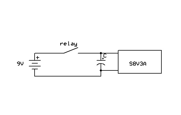
I got into a problem by following the advice of adding a capacitor (electrolytic 44microF) between the ground and VIN of a
Pololu Adjustable Step-Up/Step-Down Voltage Regulator S8V3A
to protect against LC spikes.
The voltage regulator was powered from a 9V battery connected through a relay (Normally Opened):
Meder SIL05-1A72-71L
The relay switch support up to 200V at 0.5A (20W) so I thought will be no problem.
The relay coil was connected on and off to 5V.
But after some tests (with load or not on the output of the regulator S8V3A, doesn’t make any difference) the relay switch began to hung in ‘Closed’ position.
When relay coil wasn’t powered the relay switch didn’t opened anymore, it remained closed.
After some readings on the internet I learned that capacitor can cause high inrush current from the battery through the relay switch.
It will protect the regulator ok, but the inrush current still exist between the battery and the capacitor thus affecting the relay switch.
If I remove the capacitor or put a resistor in series with the relay (100ohm) the relay switch do not hung anymore in closed position when the relay coil isn’t powered.
So in this case the capacitor maybe solve one problem (protect the regulator) but create another (damage the relay).
It looks like what you used was a reed relay, so I suspect that rather than “creating” another problem, what you did with the capacitor exposed another problem: that relay was never going to be a reliable part for switching power. Can you confirm that it’s a reed relay, and if so, why were you using one for power switching? (I think of them as for signal switching, but I have not ever used them.)
With a relay, you cannot multiply the voltage and current ratings together to come up with some sort of “safe amount of power”, as you did. In fact, you are not allowed to exceed either the voltage or current rating, at any value for the other parameter.
You are probably correct in that the inrush current exceeded the rated 0.5 amps, which is very damaging to the contacts. As Jan suggests, that relay was never intended to be a power switch. In general, relays are very unreliable for switching DC power.
the power rating of the relay was specified in its datasheet, I assumed I’ll never exceed either the voltage or the current.
The consumer connected at the output of the pololu regulator will never draw more then 20mA, but I got the same situation even without any consumer connected.
Any suggestion what should I use for this power switching?
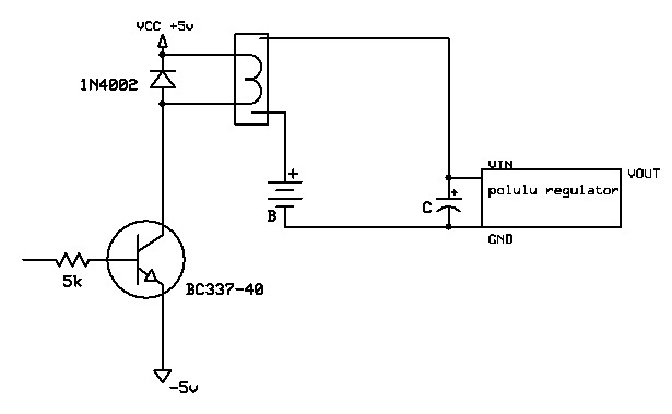
In the complete circuit the relay coil receive 5V/10mA from a BC337 when a low current is received in the transistor base.
Should I eliminate completely the relay/diode + battery and connect the pololu regulator GND to BC337 collector and pololu regulator VIN to VIN +5V?
In this case do I still need the capacitor between GND and VIN at the pololu?
There are many ways to switch power by electronics, and a relay is generally a bad choice. It would help if you tell us what you want to do and specified your circuit requirements. Are you aiming for the lowest possible power consumption while the rest of the circuit idles? Does part of the circuit have to be electrically isolated from another part?
pololu regulator power an IC555 whose output enter an buzzer. I use this variable regulator so I can change the intensity of the sound.
The base of the NPN tranzistor comes from HT12D decoder which decodes the output from an RF receiver.
Whole circuit consume 4mA at idle, when the signal is received the IC555 + the buzzer will consume around 10mA.
Yes, I would like the lowest power consumption as the whole circuit is powered by 6xAA batteries.
I don’t think the IC555 and buzzer needs to be electrically isolated from the RF receiver+decoder part.
We have released some much more efficient regulator products than the S8V3A design. If the maximum output of 8V can work for you, this is probably the best part:
However, relays like that draw much more for just the coil current than the target current you are talking about, so it would only make sense if you need your circuit on a very small portion of the time. And if your current really is so small (10 mA max), you could put the resistor in series to limit the inrush current and use a smaller relay, though 100 ohms seems a little too high.
Right, you wouldn’t need the extra capacitor. You should also look at your input voltage with an oscilloscope so you can see how much of a problem you have (if any) and to confirm that you have fixed it. A nice bonus with the resistor is that if your circuit is battery powered and isolated from everything else, you can use your scope across the resistor to see exactly how high your current is getting when you turn on the relay.
I’m wiring up stepper motors using the tiny 4988 controllers. I’ve read the article on LC voltage spikes.
I know I need an electrolytic capacitor as close to the board as possible.
The motors are Vexta PK266-02A, 2A, 1.8 Ohm. I plan to run them at 12 volts, 1-2 A per coil depending on the required torque I wind up needing.
Is a 35V 330 uF capacitor appropriate? I have some larger capacitors in the 1000uF range. I also have some 50V 33uF capacitors. I’ve got some 16V rated capacitors in the 100 uF range. (I think I am describing the units appropriately, the symbol preceeding the F looks like a Greek “mu”, I assume it’s picoFerads but I’m way out of my depth here)
Is bigger better? How big is big enough? Does the initial transient spike mean I need a capacitor capable of dealing with the maximum voltage point of the highest spike?
Should I use one of your electronic switches close to the controller board as well, then energize the overall system, and only then use your electronic switch to supply power to the stepper board, hopefully avoiding the transients issue alltogether?
Is there a combination of these things that would be best?