The 330 uF cap should be plenty. Even the 33 uF might be enough if your power wires aren’t really long. The 16 V cap is probably on the low end for your 12 V application. Part of what will help you is that you have quite a bit of margin between your 12 V supply and the 35 V maximum of the board, so even if you get a 15 V spike, you’re still safe. If you were trying to run at 24 V or higher, I’d be more concerned.
That symbol is the greek mu and it stands for micro (10^-6), not pico (10^-12). Pico is abbreviated with a “p”, nano (10^-9) is abbreviated with an “n”. The units of capacitance are “farads”.
“We also see that the frequency of the oscillations is just under 100 kHz, which with a capacitance of approximately
9 uF indicates that the wire inductance is a few hundred nH, which is consistent with what we would expect for the
36” leads."
Just finished this article. Awesome read. For us aspiring electronics students, can someone please go through the calculations that were used to calculate the inductance as a few hundred nH? The math is what really interests me here. Which forumale were used to arrive at this conclusion. Thank you.
I think the main calculation was based on f = 1/(2pi*sqrt(LC)) and the secondary calculation of wire inductance based on its length was just using some table lookup or online calculator of inductance of a wire. I tried the first few wire inductance calculators I found just now, and the results I’m getting now are 5x bigger (1-2 uH instead of few hundred nH).
Hi Everyone,
Regarding the LC voltage spike, my project is in opposite direction. I want to create a voltage spike. I attempted a a simple equivalent circuit with 9v battery cell. I simulated the circuit on multisim and the result was voltage spike with a decaying oscillation after the closing the switch. However, when I build the circuit with the same values as in simulation, the resistor smoked. The resistor was capacitor, inductor, zener diode and resistor in parallel. (220uf, 1mH, zener 11V, 6.6ohm). I missed something in simulation.What it is? My goal was to use weak source of energy (4.5v, and low current in pulses) to charge battery. (about 10 ohm equivalent) That is why I created and equivalent circuit. My objective was to use that equivalent circuit (oscillator) beef up voltage passively with minimum loss of energy in process. Similar to the transformer except that transformers do not work and are dissipative. I appreciate more ideas on those LC voltage spike application notes and circuits.
If you programmed the simulation correctly, it would have oscillated for just a few milliseconds after switch closure. After that time the circuit settles into steady state in which the resistor just heats up, dissipating the battery energy.
If you want to charge a battery from a low-voltage source, you are on the right track, as either an inductor or transformer can increase the supply voltage (but not without losses due to internal resistance). However, you need to maintain the oscillations with an active device called variously a “boost converter”, “boost regulator” or “voltage step-up”. See for example pololu.com/catalog/product/799
Hello,
Thanks for reply and suggestions. I reviewed the specs of the voltage step up device and I believe it is not suitable even though it is doing what I am attempting to do. The problem is that my available current source is in 5mA at most at 1.5V or 4.5V. The source is charged up electrolytic capacitor of 100 uF.
The problem with my simulator is that it does not have ability to tell the difference between ceramic capacitor and electrolytic capacitor (ESD) and power rating for resistor.
I recommend the LTSpice schematic design and circuit simulator package, which you can download for free.
It is certainly possible to create a very simple voltage step up circuit, that will operate on very low currents and voltages (for example using a single 0.5V solar cell at 10 mA), but the efficiency will usually be poor. Basically any transistor oscillator working in the audio frequency range, connected to a small transformer, can be used to generate high voltages at low current. The “joule thief” is an example overunity.com/13175/25mv-jou … nergy-247/
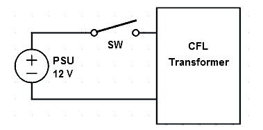
Hello everyone, I need some electronics help with a problem that I think has to do with a voltage spike. I have a CFL backlight connected to the 12V rail of my HTPC and controlled by a physical switch:
The problem is, if I turn the backlight on while the PC is powered, sometimes the PC will hard reset. I suspect that powering up the backlight causes a voltage spike that will sometimes trigger short-circuit protection in the PSU.
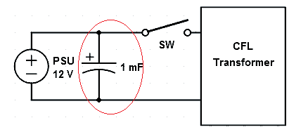
I was told that adding a large capacitor BEFORE the switch may get rid of the voltage spike when the backlight is turned on. From what I understand it should be wired like this:
However, the spike still occurs sometimes. Does anyone here know if this is the right approach? The capacitor is not connected right next to the switch but a short distance away with jumper wires. Might that be the problem? Do I just need a bigger capacitor? Any help is appreciated, thanks!
I suspect that your problem is not being caused by an LC voltage spike (if it was, the symptom would be problems with your load and you would want to put your capacitor on the other side of the switch as close to your load as possible). Rather, it sounds like your CFL transformer is drawing a large initial burst of current, which is straining your power supply and causing voltage to drop and your computer to reset. In that case, putting a large capacitor on the supply side of the switch (where you have it in your diagram) can help. I think you should try a larger capacitor; if you continue to have problems, you probably need a more powerful power supply.
By the way, just so there is no misunderstanding, is the 1mF in your diagram referring to milli- or microfarad? I have seen microfarad represented as mF before, and larger capacitors are typically represented in units of microfarads (e.g. 2200uF).
Thank you for the help and info! The problem was indeed a large initial current draw. Using a bigger capacitor did reduce the occurrence of the crash a bit, but interestingly, replacing the rocker switch I was using with a push-button switch eliminated the crashes entirely.
The capacitor I was using was indeed 1000uF. I now have a 3200uF capacitor connected right before the switch.
Again, thanks for the help!
jan, Thnks for sharing this Information.
I am facing same problem while I am using the relay to charge and discharge capacitor bank. Charging voltage is 80V DC and current 5 to 10A DC. While i am trying to monitor the voltage with my controller and voltage monitor IC, IC and controller gets burnt.Please suggest solution.
Without knowing about more about your setup, it is hard to say whether your problems are related to LC spikes. Also, 80V at 10A is pretty high and potentially very dangerous to work with, and especially since things are already getting damaged, I strongly suggest that you find someone knowledgeable with high power electronics to help you if you are not completely sure of what you are doing.
Jeremy,
Actually my task is to monitor super capacitor board, charging-discharging voltage and current. For few cycles of iteration it works fine. Even though I have provided zener to to clamp voltage at input pin of voltage monitoring IC. Still after some operation IC gets damaged.
Thanks for the suggestion; we’ll try to make it clearer. The main solution is, if you can, stick a large electrolytic cap across your power input, close to your ceramic capacitor.
I have some LED motion sensor lights that use 4 D size batteries that I use at a cabin, they draw 143mA. I want to hook these up to my 24v battery bank. I ordered some D24V5F6 voltage regulators (6V, 500mA Step-Down). I tested the lights using the voltage regulators with a bench top power supply and used something like 100v 50μF electrolytic capacitor to protect the regulator. The lights and regulator worked fine. My cabin is connected to my batteries with 2 sets of 10 gauge cables run in parallel about 140 feet long (I needed larger than 10 gauge but already had a bunch of 10 gauge landscaping wire so I just double it up). My question is how large of a capacitor do I need if I’m connecting these voltage regulators to these long large cables? Or even better how to I calculate it?
We are missing some details about your system, like why you are using such huge cables and what you are powering with your battery bank, so it is difficult to determine how much capacitance you will need. You will probably have to test the regulator and LED motrion sensor lights in your system to determine what works. You might start with a few hundred uF.
The battery bank is four 6v deep cycle batteries connected in series to power lights in my cabin, which is 140 feet from my battery bank – if you’re asking why I just don’t move the batteries closer to the cabin it’s because the cabin is in the trees and the batteries are next to the solar panels which are in a clearing in the sun. Two 10 gauge (5 mm^2) wire equates to about a 7 gauge wire (about 10 mm^2). So with 2% lose I can still only push 2 amps at 24vdc or a whopping 48 watts. Anyway there is a path along which this cable runs that I’m going place these motion sensor lights, each of which pulls about 143mA.
It is unclear to me how you calculated 2A for 2% loss in your system. With a single 10 gauge wire, the resistance of the wire is about 1mΩ/ft, so with a 280ft cable (down and back), the voltage drop across the cable flowing 2A would be about 0.56V, which is about 2.3% loss. Also, where is the 2% threshold coming from? With something like our regulators, you get some of that efficiency back when their input voltage is lower. Anyway, it sounds like you already have it all installed, and the fact remains that the bulk of your system power is going to the lights in your cabin, and we are not sure how they would interact with the cables and what kind of voltage fluctuations there would be. Still, a few hundred uF at the inputs of the regulators will probably be fine.