Shunt regulator with external Resistor

Hi,

I’m using the Pololu 26,4 V 2,8 Ohm 15 W shunt regulator for a 24 V 500 W motor. After a few minutes of use it burnt up.

I guess I need to be able to sink more power than 15 W.

I took a look at this Pololu website:

The first picture looks like I could just order another 26,4 V 15 W shunt regulator and add an additional resistor capable of high load. Is that correct?

I’m thinking about using a 100 W resistor. But I’m not sure about how much Ohms it should have. Can you help me with that?

Best regards
Sebastian

Hi, Sebastian.

The shunt resistance on those shunt regulators shares the load with a FET. Can you tell if it was the resistors or FET that broke on your unit? Could you post pictures of both sides of the burnt board?

It is probably not practical to use an external shunt resistor with the #3775 version of the shunt regulator. The #3780 version is meant for adding an external resistance and its set voltage can be adjusted with an external potentiometer, but lets determine how your unit broke before considering that.

-Claire

Hi Claire,

thanks for your support. I’m pretty sure the resistors themselves got too hot. The FET looks good to me.

What is the procedure to set the 26,4 V as a set point for #3780? How many ohms sould the potentiometer have at max?

How many ohms should the external load resistor have?

Best regards,
Sebastian


Edit:
I found the procedure to set the set point voltage as well as the max potentiometer resistance at the end of the link i posted in the first post of this thread.
But the question “how many ohms for the external load resistor” still remains.

A power resistor of 3 to 4 ohms is probably good.

By the way, since you mentioned the FET seems okay, you might be able to just add the resistor to your current board. First you should check that the resistors failed open (measure as high impedance). If that is open, you can measure the resistance across the FET to see if it’s over 1kohm (the multimeter measurement will jump around and take some time to settle as you measure it). If the measurement quickly settles below a few ohms, your FET is also broken. Here is a picture that shows where you can measure:

-Claire

Wow, thanks for the excellent support! I’ll try all that.

One last question: is the “3…4” ohms based on experience or is there a way to calculate the value? Just so that i can solve problems like that by myself in the future.

I did my own high school level calculations with 3 ohms and that resulted in 232 W going through the high load resistor at 26,6 V. This would be roughly double the value the resistor was made for, but i guess that’s ok because its only for short periods of time.

There is not exactly a straight forward calculation. Increasing the resistance of the shunt resistor increases the amount of the load it dissipates. The on-board resistors were already taking more load than they could handle given that they burnt, but all together they were only rated for about 25W, so If you use a higher power resistor to replace them, the resistance can also be increased to take extra load off the FET and keep it from breaking. The 232W you calculated is the approximate maximum power a 3 ohm shunt resistor can dissipate while still regulating the voltage to 26.4V, so I recommend using a 250W resistor, but if you already have something that is 100W, you could try it.

As for the power rating of resistors. Generally, the power rating is for average power and the maximum the resistor can handle for short durations is several times larger. Their datasheets sometimes have a graph that shows peak power or energy vs. surge duration. You could also look for resistors specifically intended for handling pulses of power; called surge or pulse resistors.

-Claire

Thanks for the explanation Claire.

I burned up another shunt regulator yesterday.

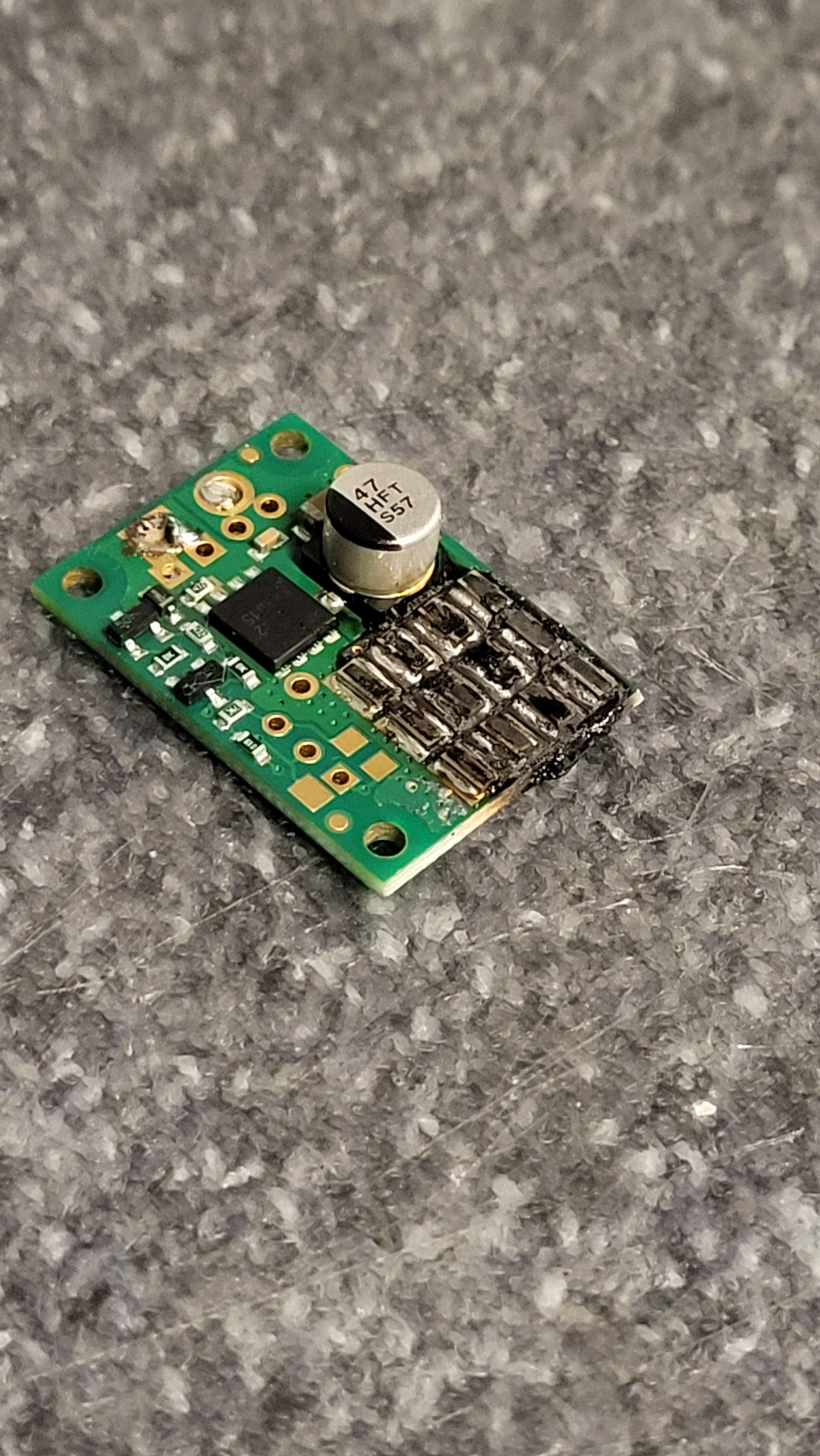
This time it was a #3780 with external 3 Ohm 100W resistor. I also added a trim potentiometer and adjusted its resistance so that the shunt becomes active at 26,4 V.

To achieve the voltage value I connected the shunt regulator to a power source where i can set the voltage as well as the max current. I set max current to 30 mA not to break anything. Then i played with the voltage and pot resistance until the switch from “constant voltage” to “constant current” happened at 26,4 V. I made sure that the 30 mA was only flowing for about a second each time.

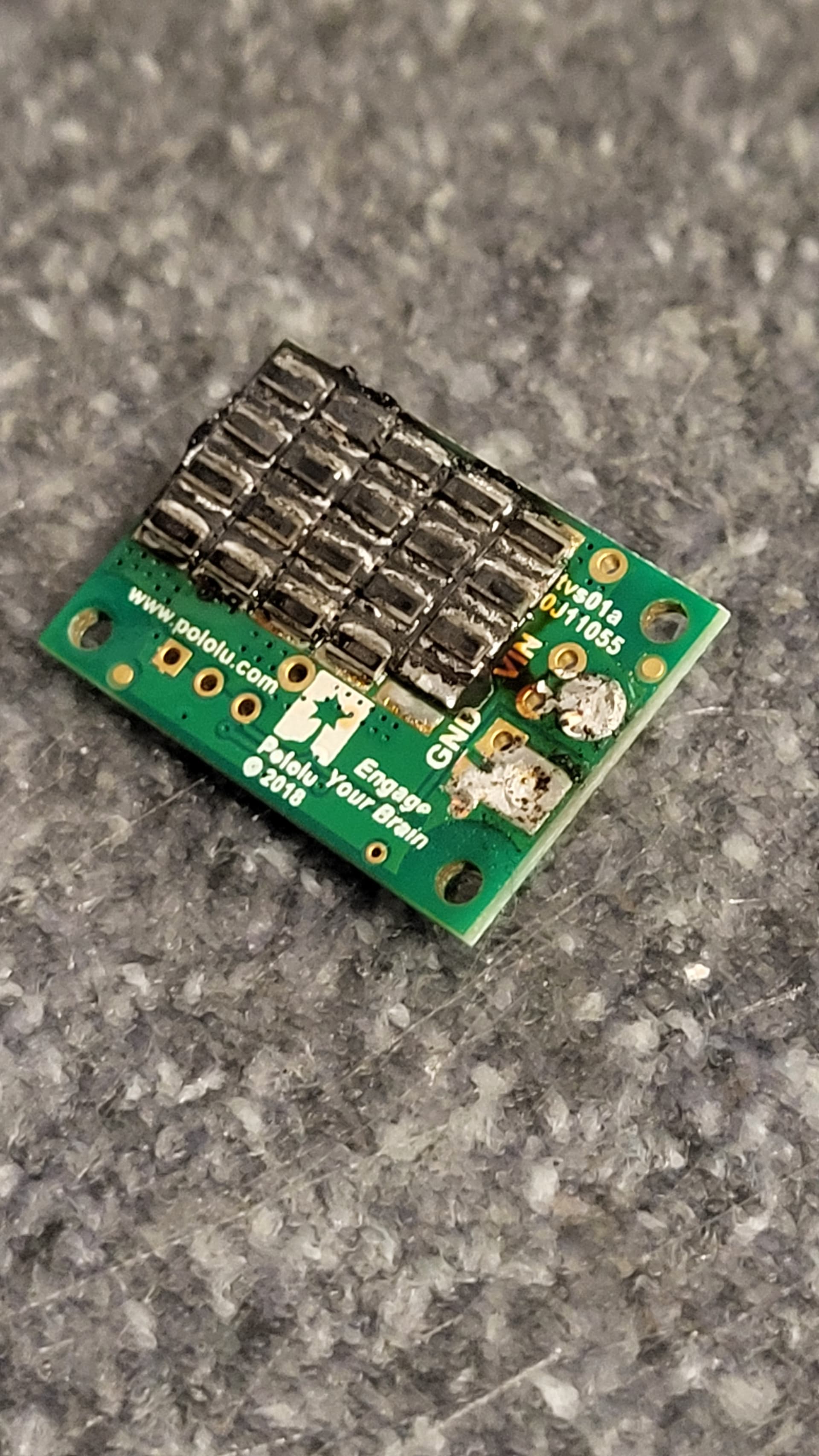
I wanted to closely monitor the temperature of the shunt regulator, especially as it took so long to get it all assembled and adjusted. So i applied a very restrictive PWMmax value to the motor driver, so that if the shunt got hot, i would have time to react. Well, it did get hot. Because of the relaxed settings, this time there is hardly any visible sign of damage. I switched everything off as soon as i felt the resistors got hot and measured the resistance of the resistors as well as the FET, like you described.

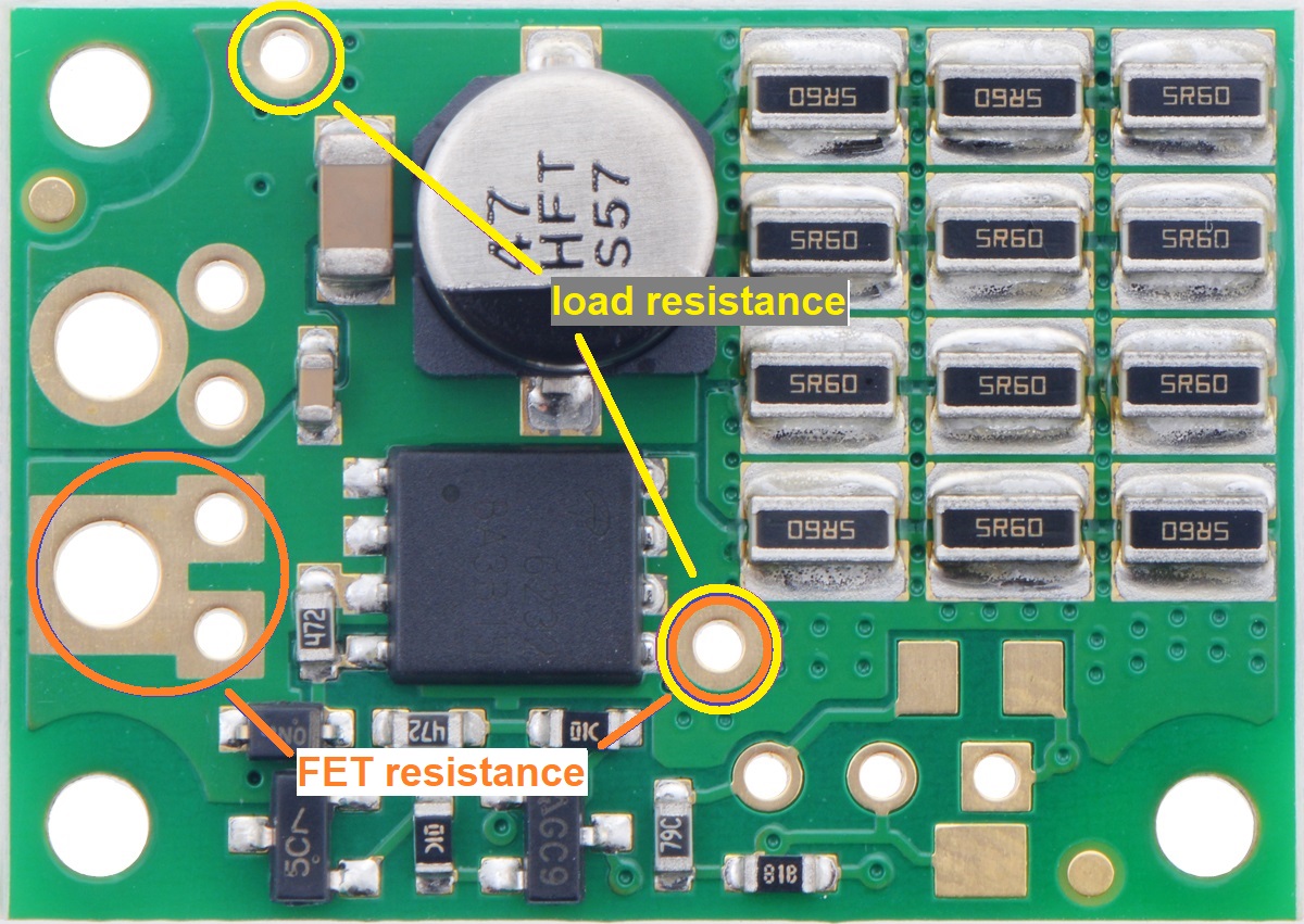
Turns out the resistors themselves have exactly the expected value. But the FET seems to be damaged as is it only has about 10 Ohms. I dug out one of the #3775 shunt regulators i burned up a couple of days ago out of my trash can and repeated the same measurements. Same situation here (resistors with expected resistance, FET only with a couple of ohms).

It seems like the FET was the part that died first and then short circuited the board, killing everything else.

Do you have any advice on this situation? Why are my FETs dying? What can i do to prevent that from happening?

I just build another #3780 shunt regulator (added external resistor and trim pot, and adjusted trim pot make the shunt work at 26,4 V). I checked the FET resistance at it was about 70 kOhms, constantly rising. I guess thats ok.
Then i applied a tiny bit more voltage, so that the power supply switched to “constant current” mode, limiting the current to 30 mA. I measured the voltage across the FET and the resistors found that 100% of the applied voltage dropped off across the FET and 0V across the resistor.

Is this normal? Doesnt that mean that all the heat will be dissipated in the FET and the resistors do nothing until the FET died?

The voltage drop across the resistor is dependent on the current. Since you were limiting the current to 30mA, the highest voltage drop your 3 ohm resistor could have is 90mV. That is why the procedure for adjusting the set point voltage on the shunt regulator product pages recommends a current limiting resistor of at least 500 ohms.

Since the FET died in you motor driver application too, it must be taking too much load there also. As I mentioned using a higher shunt resistance takes load off the FET but you can only go so high for a given current without the shunt regulator losing the ability to clamp the voltage. I probably should have recommended it sooner, but before doing anymore testing or troubleshooting, you should use an oscilloscope to look at the frequency and power level of your system’s spikes.

-Claire

So i need a resistor thats big enough so that the FET doesn’t burn up, but small enough so that the overvoltage protection of the PSU doesn’t kick in.
And without knowing the height of the voltage spikes, there is no way to know which resistance would fit. Then there’s just trail and error and some burned up FETs along the way.
Makes sense.

I’ll look into oscilloscopes. There is a wide range of features (and prices associated with them). Can you give me any advice on what features are important for this particular task at hand?

I read the procedure to adjust the voltage set point and it said the current limiting resistor should be “at least several hundred ohms”. I didn’t want to burn up yet another shunt regulator, so i used 1kohm. I did not use current limiting on the lab PSU in combination with the current limiting resistor.

What i found was that there was no singular voltage value where the current suddenly increased. If i remember correctly, the current remainded at 0 until i approached the set point and then rose about 1 mA for every 0,1 V. So more like a slow and steady increase of current, while i was expecting a sudden jump. It didn’t feel like a set point, more like a “set area”.
I didn’t know how to adjust the pot to calibrate the set point this way. Thats why i switched to current limiting in the PSU and took out the current limiting resistor. That way i got my jump in current - at one voltage the current was 0, at 0,1V more i was at the current limit of 30mA. This makes it easy to calibrate the set point using the pot.

I will try again with current limiting resistor of 500 ohm and no current limiting in the PSU. I expect the current to slowly rise again (but not as slowly as with 1kohm) if I increase the voltage. Do you have any advice on how to determine where on this current ramp the set point lies?

When measuring the voltage set point with a current limiting resistor as shown on the shunt regulator product pages, you just need to apply a voltage that is higher than the set point and then measure the voltage across VIN and GND on the shunt regulator. The voltage across the shunt regulator is the set voltage and it should be less than the applied input. The current from the source will continue to rise as the input rises because the voltage drop across the current limiting resistor is increasing.

I do not expect you will need any special features or a particularly high bandwidth to measure spikes from a motor driver system. I suggest looking up some guides on picking entry level or hobby oscilloscopes, like this one from HowToMechatronics. That article is getting old so there are newer and better low-cost scopes from manufacturers like Rigol (DHO804) and Siglent (SDS804X HD). (We have not tried either of those scopes.)

-Claire