
I write this post in part to seek advice on a couple points, and in part to document my stumbles so that others with an Arduino Zero and XYZrobot smart servos (A1-16) might benefit. Also, to share a bit on Pololu’s forum as I’m pretty stoked on this site/vendor and those involved!
I’m building an 8 legged robot I call Arachnobot that will have 8 stepper motors and 16 of these smart servos for motion, along with a whole bag full of other tricks I’m looking forward to fleshing out once I nail down a solid motion API that suits my needs.
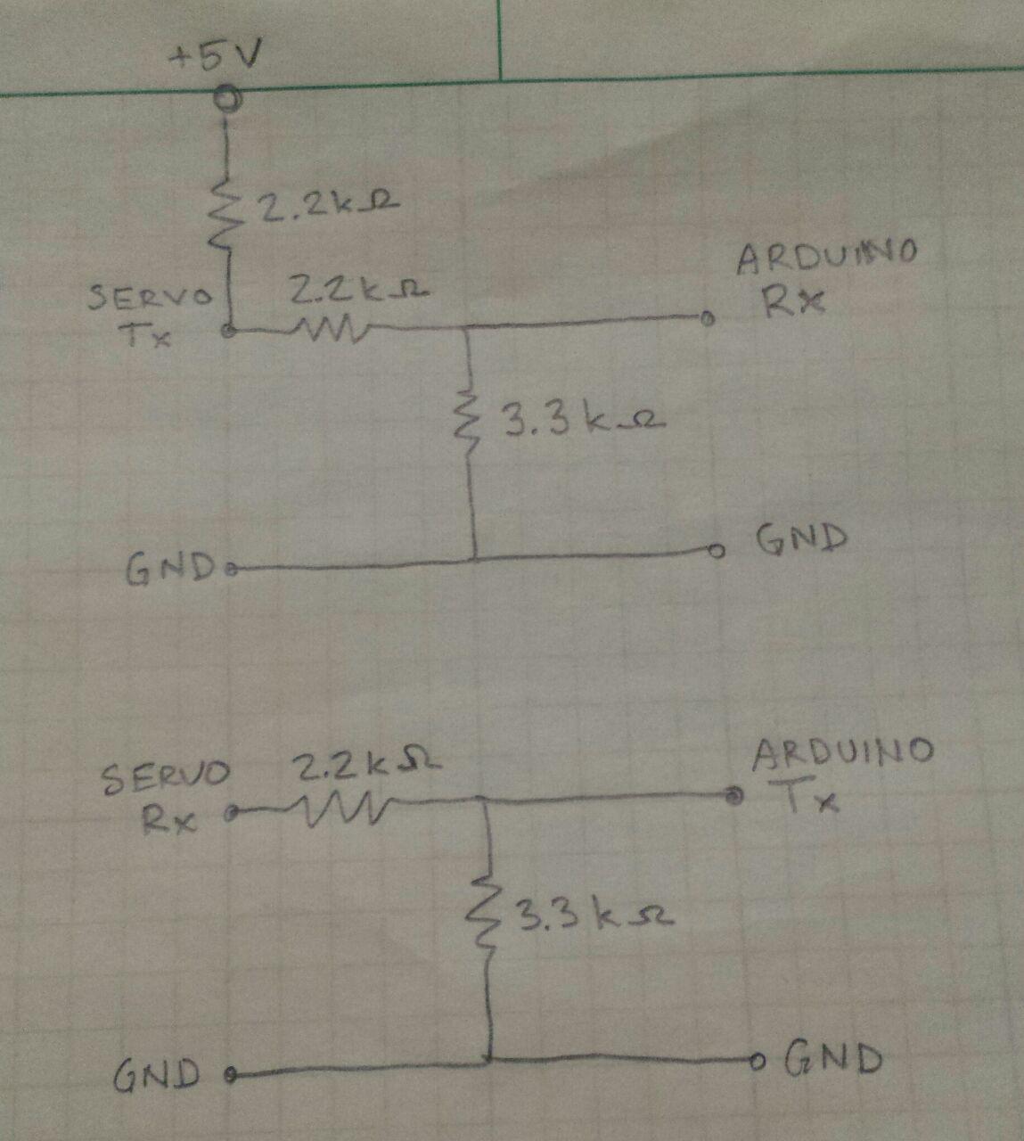
A note for anyone else with an Arduino Zero: it has a dedicated serial port using pins 0 and 1, and so you don’t need to include SoftwareSerial.h to simulate a serial port on other Arduino digital pins. IMPORTANT NOTE: The Arduino Zero operates at 3.3V and so I had to put a simple voltage divider on both Tx and Rx lines with R1 = 3.3 Ohms and R2 = 2.2 Ohms to shift the 5V TTL that these servos operate at to the necessary 3.3V needed on the Arduino Zero.
========Power Supply========
From what I’ve read, these XYZrobot servos are rated to use a supply between 8 and 12V, and to get the most power out of the servos it’s good to supply with 1A per servo. I see on Pololu’s site they mention 500mA at motion, but aren’t there starting currents that exceed this when looking for quick motions?
For initial testing, I’m using a bench power supply I built a long time ago that is limited to a 1A supply (more like 750mA as it’s old) to power 2 daisy chained servos and I was successfully able to run Pololu’s Arduino projects; DetectServos and PlayAnimation using an Arduino Zero’s pins 0 (Rx) and 1 (Tx). I LOVE Pololu and am very thankful these projects were available as XYZrobot’s projects are in C++, they have no examples, light documentation, and my skills in C++ are shaky at best.
I daisy chained 2 servos off this power supply, and I notice the supply sagging (voltage drops from 11V) quite a bit because my homemade power supply isn’t able to deliver the needed current. I then grabbed an old AC-DC converter that supplied 12.4 @ 1.5A. This killed one servo. Luckily it didn’t kill the servo that was daisy chained off of the servo directly connected to the AC-DC converter, nor my Arduino Zero. It’s a huge disappointment that these servos aren’t tolerant of anything over 12V. I recall reading some documentation that to get maximum performance (25kg-cm) it is best to operate at 12V supply. Or maybe there other subtle (grounding) issue that killed the servo? Either way, I will be sure to supply with no more than 11V just to be safe.
I opened the dead servo up and found that Vdd was at zero volts on the Microchip PIC inside (http://www.microchip.com/wwwproducts/en/PIC18F25K22), but don’t have time to spend chasing down what component failed. Any suggestions on what component might have failed due to this “high” voltage? I’d be willing to do a component swap considering it’s not a BGA chip I’m replacing as I’m not equipped.
I then took out a 4,000mA 30C 2S LiPo (dead at 6.0V, full at 8.4V) and verified that DetectServos and PlayAnimation worked without voltage sag. All was well. Now to try to read from the servos.
========Serial Pull Up Resistor========
I then wanted to see if I could read values from the servos and so I tried running ChangeId and ReadEverything, and got bad responses like this:
ReadEverything response
status:
statusError: 0x10
statusDetail: 0x60
pwm: 0
posRef: 333
position: 333
iBus: 1
error reading RAM: 2
error reading EEPROM: 2
ChangeId response
Send “y” to change the ID.
Trying to change the ID…
Error: Failed to read ID from EEPROM: code 2
Though note that even though it spits out this code 2 error it still changes the servo ID. Did I miss it in the data sheet, or where can I read about these error codes?
I changed only the address of the servo and left the baud at 115200 in both sketches. I found that the Rx (Arduino) / Tx (servo) line needed a pull up resistor with a relatively clean 5V supply. Watch to be sure you have grounding correct! I’m not sure what pull up resistor to use and I tried a few (10k, 4.7k Ohm) and settled on 2.2k Ohm. Any suggestions on how to choose a pull up resistor?
I used a SUNKEE buck-boost I had laying around (IN: 3.5-28V, OUT: 1.25-26V @ 1A, 3Amax) that had ~150mVpp in the 10s of kilohertz range (read up on 1/f noise) of switch noise on the output as it bucked down from the battery voltage to the 5V needed for the pull up. Note that I left the buck-boost output ground wire disconnected so as not to create a ground loop. I got good responses from ChangeId and ReadEverything. See a typical response at the very bottom (as it’s long). Though often there are values for statusError and statusDetail that aren’t in the datasheet, or don’t make sense. For example:
statusError: 0x10
statusDetail: 0x50
statusError: 0x10
statusDetail: 0x60
I added an RC filter to the output of the buck-boost thinking it would improve things. R = 4.7k Ohm, C = 4.7nF for a low pass cut off around 7k Hz. It cut the output noise in half in the 10s of kilohertz range, however this filter ruined comms and I was back to similar errors shown above. It didn’t matter if ground was tied only to the battery, or only to the buck-boost output, it only spit out errors shown below. Any ideas where I can read up on these error codes?
error reading status: 3
error reading RAM: 2
error reading EEPROM: 2error reading status: 5
error reading RAM: 4
error reading EEPROM: 2error reading status: 5
error reading RAM: 3
error reading EEPROM: 2
Now that I have this working, I will be creating a sketch for this Arduino to control 16 of these servos over TTL serial, while it controls 8 of Pololu’s Tic T834 stepper controllers over I2C. I welcome any suggestions to reduce electronics (weight) by using a different power architecture as I’m likely going to need several DC-DC boost converters to drive the servos and steppers. I’d like to use these LiPos I currently have for this project.
Pololu Rocks!~!
Cheers,
Action

FRESH OUT THE BOX SERVO READEVERYTHING RESULTS:
status:
statusError: 0x40
statusDetail: 0x0
pwm: 0
posRef: 513
position: 513
iBus: 1
RAM:
sID: 1
ACK_Policy: 1
Alarm_LED_Policy: 0
Torque_Policy: 1
SPDctrl_Policy: 0
Max_Temperature: 75
Min_Voltage: 119
Max_Voltage: 232
Acceleration_Ratio: 0
Max_Wheel_Ref_Position: 1070
Max_PWM: 1023
Overload_Threshold: 255
Min_Position: 23
Max_Position: 1000
Position_Kp: 3840
Position_Kd: 2048
Position_Ki: 0
Close_to_Open_Ref_Position: 1023
Open_to_Close_Ref_Position: 0
Ramp_Speed: 1023
LED_Blink_Period: 0
Packet_Timeout_Detection_Period: 10
Overload_Detection_Period: 40
Inposition_Margin: 1
Over_Voltage_Detection_Period: 255
Over_Temperature_Detection_Period: 10
Calibration_Difference: 248
Status_Error: 64
Status_Detail: 0
LED_Control: 1
Voltage: 172
Temperature: 26
Current_Control_Mode: 2
Tick: 201
Joint_Position: 513
PWM_Output_Duty: 0
Bus_Current: 1
Position_Goal: 521
Position_Ref: 513
Omega_Goal: 0
Omega_Ref: 0
Requested_Counts: 0
ACK_Counts: 11
EEPROM:
Model_No: 1
Date: 15-11-18
Firmware_Version: 4
Baud_Rate: 12
sID: 1
ACK_Policy: 1
Alarm_LED_Policy: 0
Torque_Policy: 1
SPDctrl_Policy: 0
Max_Temperature: 75
Min_Voltage: 119
Max_Voltage: 232
Acceleration_Ratio: 0
Max_Wheel_Ref_Position: 1070
Max_PWM: 1023
Overload_Threshold: 255
Min_Position: 23
Max_Position: 1000
Position_Kp: 3840
Position_Kd: 2048
Position_Ki: 0
Close_to_Open_Ref_Position: 1023
Open_to_Close_Ref_Position: 0
Ramp_Speed: 1023
LED_Blink_Period: 0
Packet_Timeout_Detection_Period: 10
Overload_Detection_Period: 40
Inposition_Margin: 1
Over_Voltage_Detection_Period: 255
Over_Temperature_Detection_Period: 10
Calibration_Difference: 248