Hopefully someone will be able to help me with this.
HARDWARE
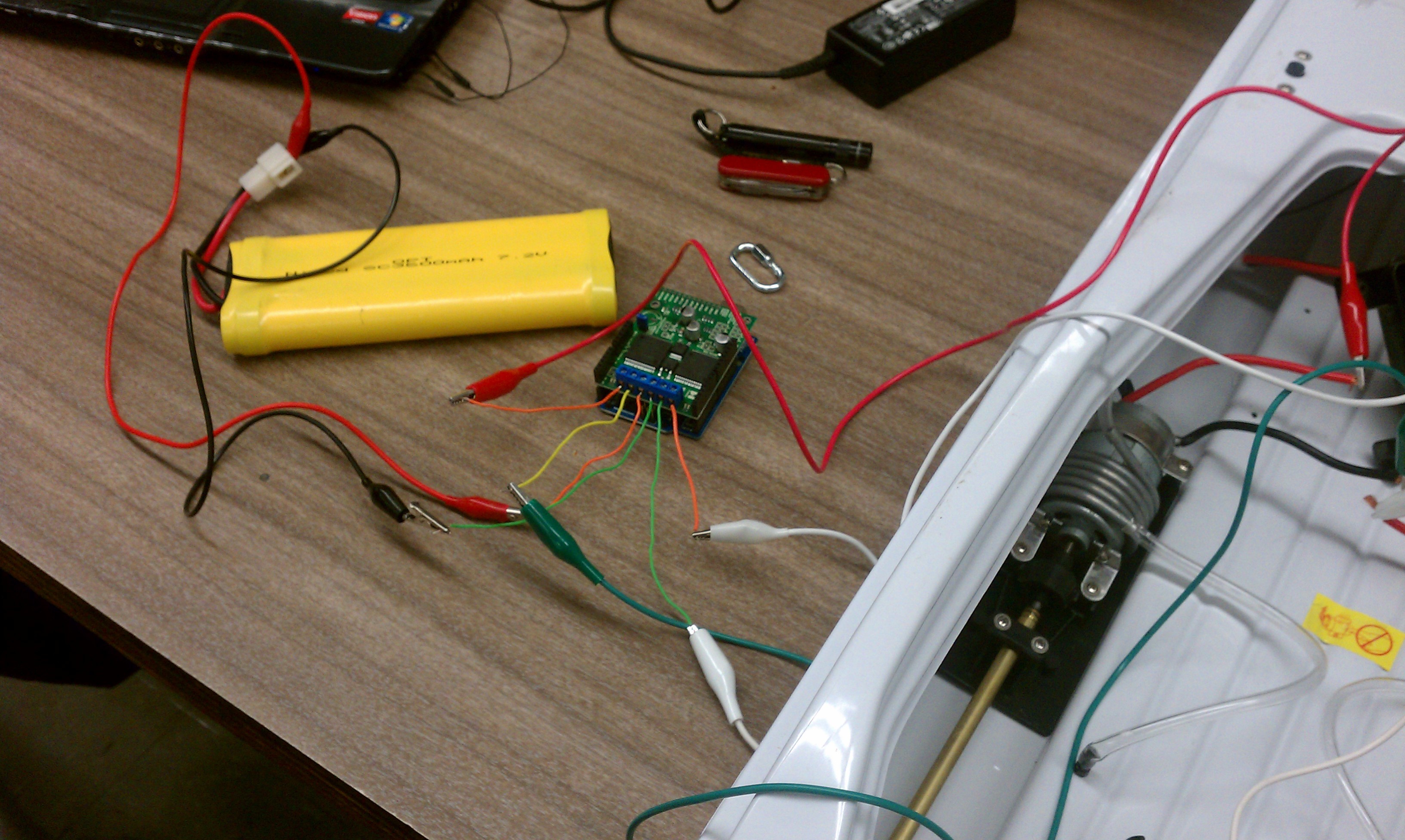
I am using the VNH5019 motor controller with the Arduino Uno to drive two motors from an electric boat kit. The motors I am trying to drive take roughly 3 Amps, per motor, when being operated under normal conditions. This should mean that even at the worst case scenario the motors would have a stall current around 30 Amps. The battery I am using is a 7.2 Volt, 3600mAh battery that came with the boat and has been used numerous times to drive the boats motors. I have already guaranteed a full charge on the battery so battery charge levels are not an issue.
PROBLEM
I am using the motor controller exactly per the instructions on the pololu site and have used it as a power source for the entire circuit, including the Arduino, and have powered the Arduino seperately from the motor controller board. When powering from the motor controller board the circuit does not produce enough current/voltage to power the motors resulting in low squealing noise being produced by the motors with an absense of movement. Further, unplugging the battery from the motor control does not change what is happening with the motor. When powering the arduino and the motor controller seperately the power led on the motor controller board does not come on and nothing happens with the motors (movement, noise, etc.).
Therefore I think it is safe to assume that the battery power input into the board is at fault for the lack of ability to drive the motors and more specifically I believe that the battery is not providing any power into the board.
I have checked the resistance across the GND and VIN terminals, checking each individually for problems with my soldering, and it is showing 1 mili-Ohm as the resistance (the same value I get when touching the leads of the multimeter together) so it seems as if the soldering is good. I did the same test to several of the pins connected to the M1 and M2 outputs and had similar results. In fact the only anamoly I have had so far is the the pullup resistor for pin 12 to M1EN does not have a resistance of 1k, rather it seems to have infinite resistance or at least a number that doesn’t readily show on my multimeter.
Last I have tried to view the output to the motors on an osciliscope but the voltage out is extremely low and noisy.
Any help I can get solving this problem will be greatly appreciated.
Are you saying that the motors keep making a sound when you don’t have your motor supply battery connected? If that is happening, it sounds like something is going very wrong. Can you take a picture of your setup and your soldering, and tell me how you have everything connected?
Are you saying that the resistance between GND and VIN is low? It sounds like you might be shorting GND and VIN.
What points are you measuring between to get this reading?
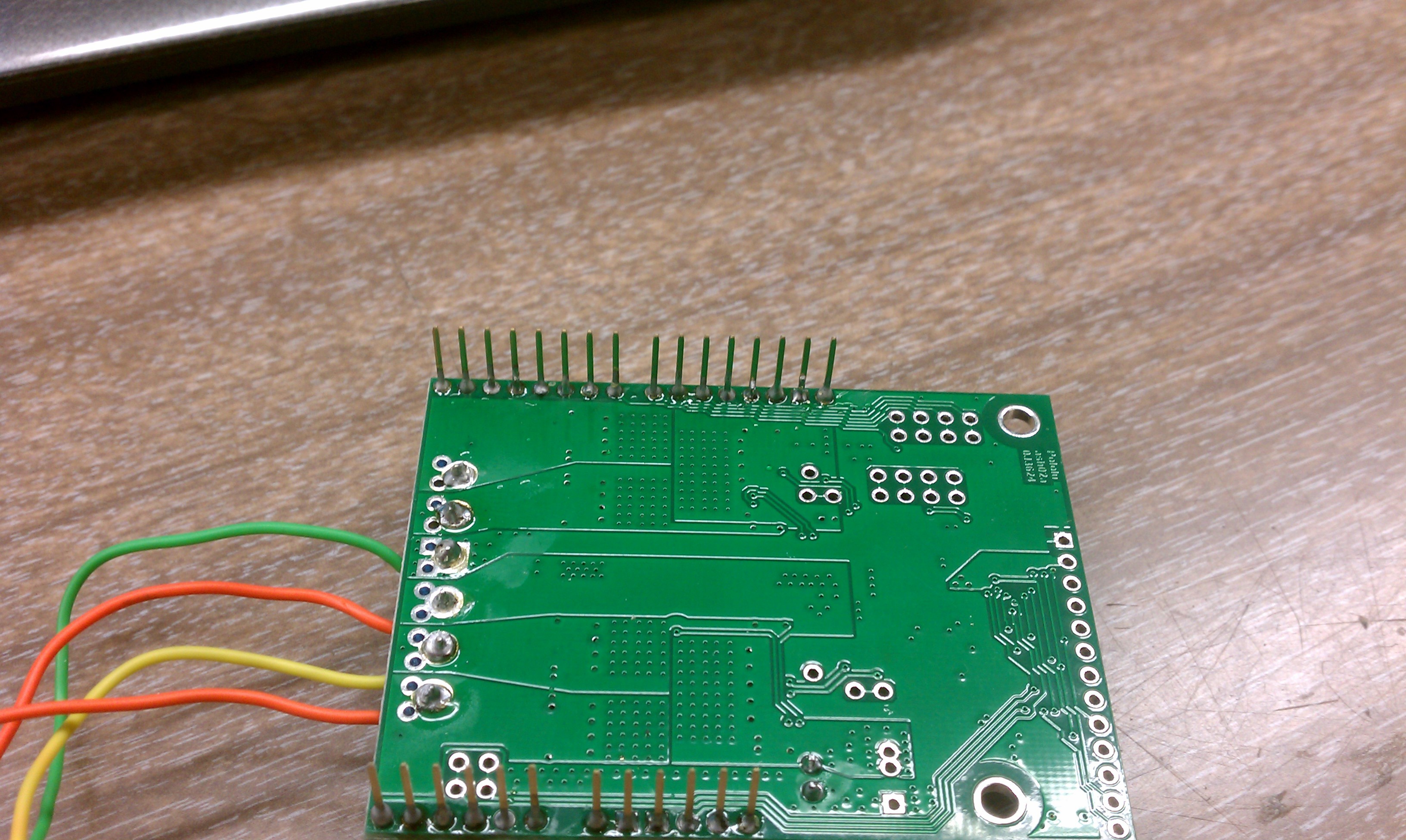
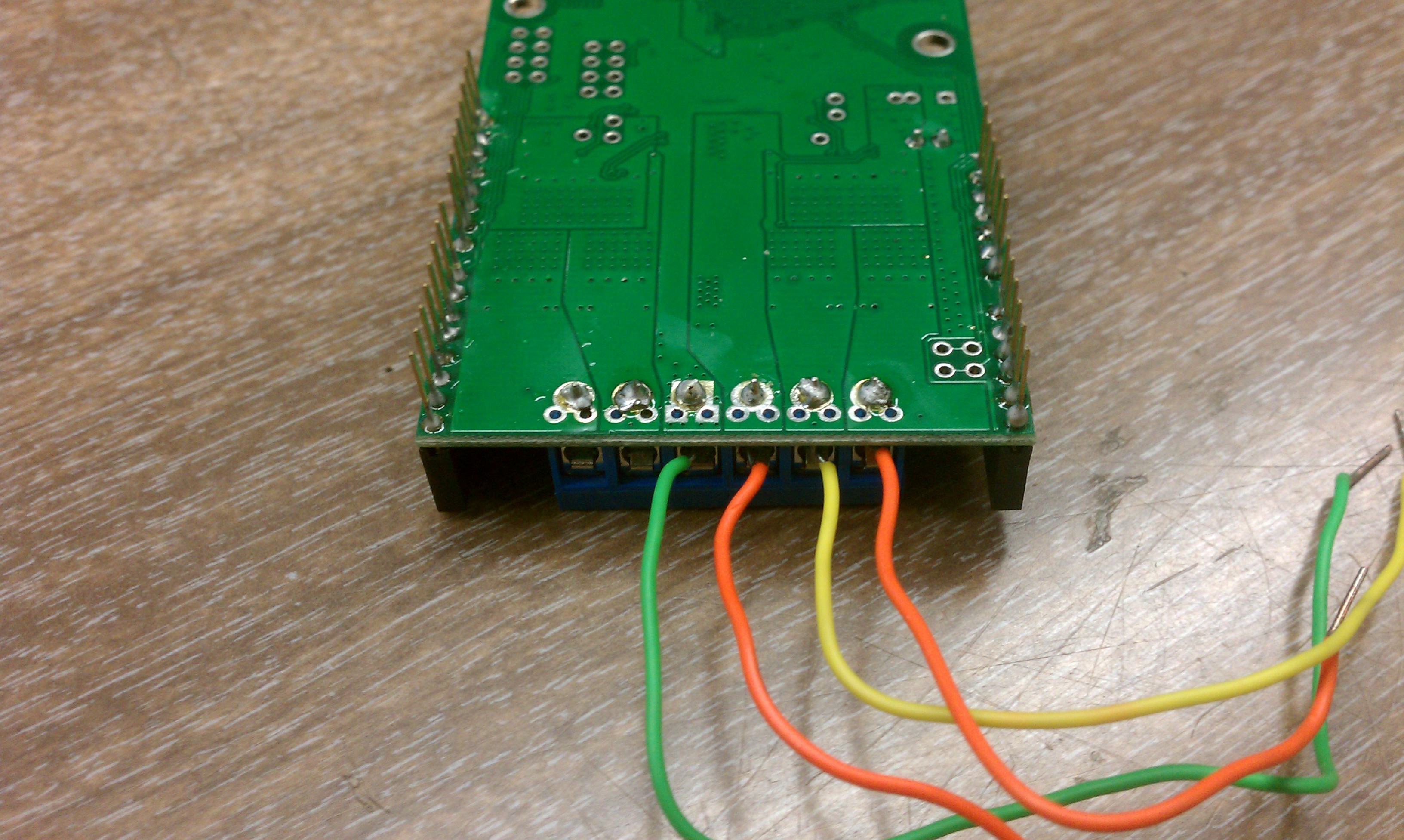
That is exactly what I am saying. Irreguardless of connection to the battery the motors will make some noise. In fact I have been able to drive a 3V DC hobby motor without connection to the battery. The pictures are below.
No. The resistance between GND and VIN is high. Resistance from the solder point on GND and into the GND terminal is low. Resistance from the solder point on VIN and the VIN terminal is low. Basically I was making sure that there was no open circuit created by poor soldering in GND and VIN (checking each terminal against itself).
From pin 12 on the driver board into the small hole that says M1EN to the left of the VNH5019 chip. Actually now that I have completed the test again I am getting a value of 1.494 kilo-Ohms. I can repeat the test using pin 2 and M2EN and I get the same value of 1.494 kilo-Ohms.
When the motor makes noise when your motor power supply is not connected, are you powering the Arduino in some way? Is the ARDVIN = VOUT jumper in place on the shield? Does the sound stop if you remove the jumper?
Your solder joints all mostly look bad, so we can’t be sure the connections are being made. The solder joint needs to be wetting the surfaces it is connecting. Take a look at this guide to soldering. If you find that it is hard to get good joints on the motor and motor power connections, you might need to turn up the heat on your soldering iron and hold it there longer.
This happens when I have the jumper on and I am powering the Arduino chip with the motor driver power supply (the 7.2V battery). The only other power connection that could be there is if the USB cable hooked to my computer and then to the arduino board itself is powering the arduino and the motor driver board. When I unhook the power supply (7.2V battery) the motors continue to make the noise.
When I have the jumper off and I am powering the Arduino seperate from the motor driver board the motors do not make a noise. In fact, the blue MOT PWR LED, on the bottom left of the board, does not turn on. This is with the battery providing power to the motor driver board only.
Certainly my soldering technique could use some work but I have had the circuit inspected by some of my professors and they all agree that the soldering while not perfect should not be a major issue. Further, I have run resistance continuity checks on every single pin soldered onto the board and I have not had any instances of a high resistance reading. Therefore, I am under the impression that my soldering has made good connections as all of the pins are reading low resistance when checked against themselves.
You can get a low resistance/continuity reading and still have a bad solder connection. For example, a small connection will have a low resistance, but not be able to handle the current. Also your connections could be intermittent and be connected by the pressure from your multimeter probes. I recommend reflowing the solder on all of the pins to create good solder joints, adding solder where necessary.
I will see what I can do about getting the chip resoldered by a more steady hand. This aside do you have any other suggestions? Thanks for the help so far.