
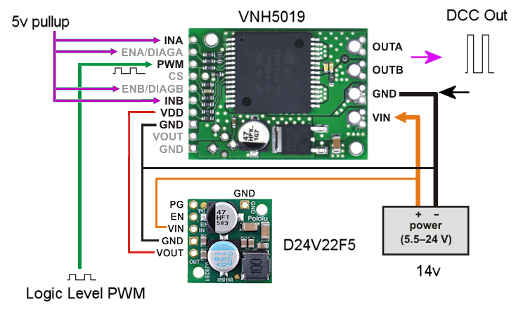
I’m thinking of driving a large amp DCC signal with this device. What I am looking for is basically an amplifier. I want to feed logic level dcc signals in and get 14v 10A out. I don’t really want to control a motor, I want the output to match the input exactly, just with more voltage and power. So, I think I understand the logic input side but I’m not real sure on the output. I’m thinking to get the maximum out of this device is to ‘slave’ the two sides together and just combine A and B out referenced to GND. But I’m not sure the best way to do that. Anyhow, here is a drawing, thoughts appreciated…
Hello.
We strongly recommend against connecting the OUTA and OUTB terminals of the driver together as doing so would create a situation where some logic inputs would short VIN to GND, which would damage the driver. It should be possible to provide 10A of current from the VNH5019 without connecting OUTA and OUTB together.
The VNH5019 is a bit different than the MC33926 we discussed in an earlier forum post.The rise and fall times of the high-side FETs on the VNH5019 is much larger (up to 250μs or 0.25ms) than for the low-side FETs (about 2 μs or less). If your DCC system is tolerant of 0.25ms timing errors, you can connect the PWM pin to 5V and switch the other logic pins according to the configurations listed in the truth table (table 12) on page 14 of the datasheet for the VNH5019.
Otherwise, you might be able to connect the positive side of your DCC system directly to VIN, the negative side to OUTB, send your DCC signal to the PWM pin, and configure the other logic pins to the “Clockwise” operating mode in the truth table I mentioned above. With this configuration, OUTB will not be connected directly to VIN or GND when PWM is low, so I am not sure how well this will work. Please note that this might not work well if you have any systems powered by the DCC output that share a GND line with the rest of the system.
Also, you might look into doing this with just a MOSFET.
-Nathan
Thanks very much for the input. I am good at the programming and logic side, not so good on the power/analog side.
I think I have found the solution however. This should give me about 4 amps which is plenty for now, not to mention WAY cheaper: