
Hi.
I am trying to determine how the current sense output of the VNH2SP30 works, but so far I have not been able to get any reasonable outputs.
I have connected your motor driver board to one of your 37D motors with 30:1 gearing ratio.
5V supply is connected and INA is connected to GND and INB to 5V.
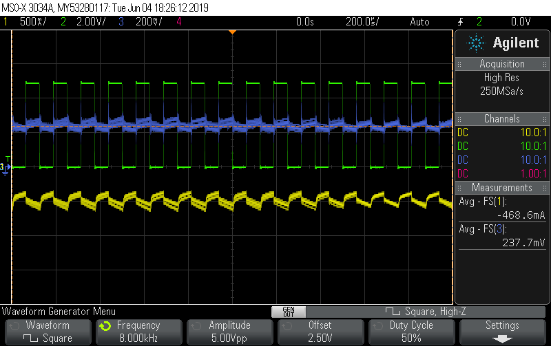
The PWM input is connected to the Wave Generator output of my oscilloscope (green signal).
A Fluke i30s probe is used to measure the current inflow into the positive side of the Motor supply connector (yellow signal).
The current sense output is measured with the oscilloscope (blue signal)
By adding a bit of friction the current consumption is around 469 mA.
In this case the current sense pin outputs a voltage of approximately 238 mV.
However when using the conversion factor from the datasheet and the sense resistor value of 1.5K (resulting in approximately 132 mV/A) this results in more than 1 A.
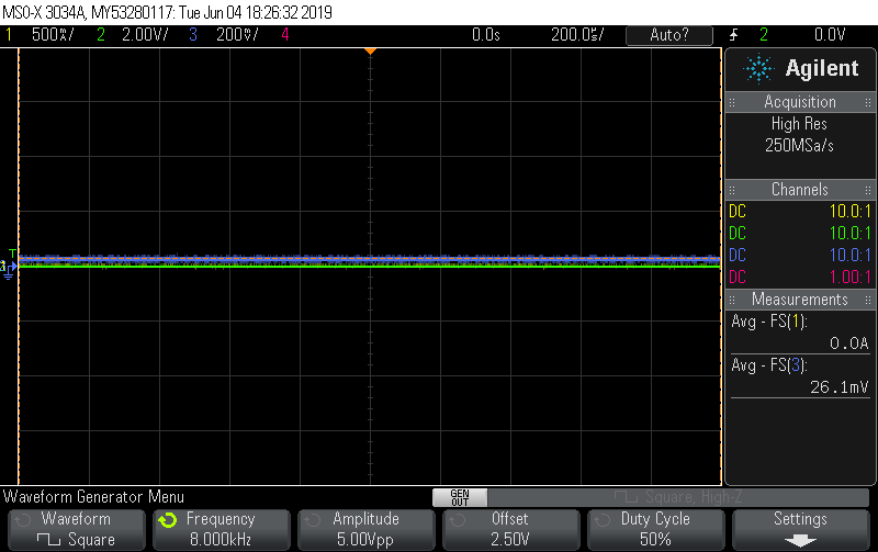
Subtracting the idle voltage on the current sense pin (when PWM signal is turned off) results in a calculated current consumption of 1.6 A which is clearly incorrect and far beyond the +/- 20% deviation that seems to be in the current sense gain.
Any explanation for this?
Best regards
Thomas Jespersen