Vl53l1x sensors from Polou

Hello,
I am currently using the vl53l1x -satel sensor from ST electronics and I am planning to replace the sensor with Vl53l1x sensor from pololu. I programming the sensor in arduino nano.
The driver used for VL53L1X from STM -GitHub - rneurink/VL53L1X_ULD at 94b88bc06ef44950ec3a5fd50b2f0287c23c5ad7
1.Can I use the same driver for the VL53L1X from pololu? cos I need to change RoI , Timing budget and so on
2.Should I change the circuit diagram also?
3.If I cant use this driver can you recommend a driver suitable for Pololu vl53l1x sensor

Thank you for assisting

Hi, Maggie.

We have not tried that library, but if it is a straightforward Arduino port of ST’s Ultra Lite Driver API, it should work fine with our VL53L1X carrier. As far as hardware differences are concerned, I think the most significant difference between the Pololu board and the VL53L1X-SATEL is that the XSHUT and GPIO1 pins on our board are not level-shifted on our board, so if you are using a 5V controller, you would need to be careful not to drive XSHUT high (our carrier already pulls XSHUT up to VDD by default).

Kevin

Can you help me understand the connection of multiple Vl53l1x pololu sensors. if the Xshut and GPIO pins is not to be connected, If it possible to get a example in circuit diagram
Thank you

Hi, Maggie.

You can still connect XSHUT and GPIO1 to a 5V controller; you just need to be careful not to drive XSHUT high to 5V, and you need to make sure your microcontroller can detect 2.8V on GPIO1 as a logic high if you are reading it.

For XSHUT specifically, which is needed to use multiple sensors on the same bus, you can drive it low to disable the sensor, then set the pin back to a high-impedance state (make the microcontroller pin an input) to let the on-board pull-up resistor pull the pin up to VDD again and enable the sensor.

Alternatively, you can add your own external level shifter(s) to XSHUT and/or GPIO1 if that is easier.

Kevin

Hello, can u tell me what is the purpose of a GPIO pin?
I am connecting multiple VL53L1X sensors to the arduino nano, since the digital pins are up to 5v , should I also add 1k resistor ?

I am fairly new to these concepts, Thanks for the guide

The GPIO1 pin is primarily an interrupt output, so if you do not need that functionality, you can leave it disconnected. (See the datasheet for more information.)

You could omit the resistors (voltage dividers) in your diagram if you are careful not to drive those pins high as I described before, but if you are worried you might do it accidentally or if you are using code that drives them high and don’t want to modify it, using those voltage dividers should work fine.

Kevin

image

Hello, Thank you for helping me .I am looking into this hardware connections and programming.
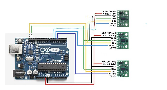
Can you please explain to me why the resistors where not used in this connection ( cos the last image I send was not of the pololu board)

Can you elaborate if the above programming set the Xshut to high impedance state instead of high(5v) and how we can add that cos I got like zero clue. (Can you explain this also in very simple terms , cos am really new to both arduino programming and electronics )
Thank you so much

The resistors should not be necessary as long as you are careful not to drive the XSHUT pins high, and they are not driven high by the program in the topic you linked. Timmy10’s program starts by driving all of the XSHUT pins low to disable all three sensors:

  pinMode(4, OUTPUT);
  pinMode(5, OUTPUT);
  pinMode(6, OUTPUT);
  digitalWrite(4, LOW);
  digitalWrite(5, LOW);
  digitalWrite(6, LOW);

Then, one by one, each sensor’s XSHUT pin is set to high impedance by making the corresponding Arduino pin an input (which allows XSHUT to be pulled up to VDD by the carrier board), and the sensor is initialized and assigned an address:

  pinMode(4, INPUT);
  ...
  pinMode(5, INPUT);
  ...
  pinMode(6, INPUT);

If you do the same thing in your program, you should not need the voltage divider resistors.

Kevin

Thank you so much for the guidance.