I tried what the code you suggested in your above message. After changing my code, the code looked as follows:
#include <Wire.h>
#include <VL53L0X.h>

VL53L0X sensor;
int pospulse = 11;
int negpulse = 12;
int clockwise = 7;
int anticlockwise = 8;


float sum = 0;

float  sensorvalue = 0;


void setup()
{
  Serial.begin(115200);
  Wire.begin();

  sensor.init();
  sensor.setTimeout(500);

  // Start continuous back-to-back mode (take readings as
  // fast as possible).  To use continuous timed mode
  // instead, provide a desired inter-measurement period in
  // ms (e.g. sensor.startContinuous(100)).
  sensor.setMeasurementTimingBudget(200000);
  sensor.startContinuous();

  sensor.setSignalRateLimit(0.25); // 0.25 MCPS

  sensor.setVcselPulsePeriod(VL53L0X::VcselPeriodPreRange, 14); // 14 and 10 PCLKs
  sensor.setVcselPulsePeriod(VL53L0X::VcselPeriodFinalRange, 10);

}

void loop()
{
  pinMode(12, OUTPUT);
  pinMode(11, OUTPUT);
  pinMode(7, OUTPUT);
  pinMode(8, OUTPUT);


sum = 0;
  float  arrayofreadings[20];
  for (int i = 0; i < 20; i++)
  {
    arrayofreadings[i] = sensor.readRangeContinuousMillimeters();
    if (sensor.timeoutOccurred()) {
      Serial.println(" TIMEOUT");
    }
    sum = sum + arrayofreadings[i];

    Serial.println(sum);
  }

  sensorvalue = sum  / 20;
  //sensorvalue = measure.RangeMilliMeter;
  Serial.println("sensor value = ");
  Serial.print(sensorvalue);
  Serial.println();
}
But it doesn’t seem to be working. Instead it stopped working at all. It gives me “65535 TIMEOUT” error.
Then I researched on internet and found that the following code might address this timeout issue.
#include <Wire.h>
#include <VL53L0X.h>

VL53L0X sensor;

void setup()
{
  Serial.begin(9600);
  Wire.begin();

  sensor.init();
  sensor.setTimeout(500);

  // Start continuous back-to-back mode (take readings as
  // fast as possible).  To use continuous timed mode
  // instead, provide a desired inter-measurement period in
  // ms (e.g. sensor.startContinuous(100)).
  sensor.startContinuous();
  sensor.setSignalRateLimit(0.25); // 0.25 MCPS

#if defined LONG_RANGE
  // lower the return signal rate limit (default is 0.25 MCPS)

  // increase laser pulse periods (defaults are 14 and 10 PCLKs)
  sensor.setVcselPulsePeriod(VL53L0X::VcselPeriodPreRange, 14);
  sensor.setVcselPulsePeriod(VL53L0X::VcselPeriodFinalRange, 10);
#endif
#if defined HIGH_SPEED
  // reduce timing budget to 20 ms (default is about 33 ms)
  sensor.setMeasurementTimingBudget(200000);
#endif
}

void loop()
{
  Serial.print(sensor.readRangeContinuousMillimeters());
  if (sensor.timeoutOccurred()) { Serial.print(" TIMEOUT"); }

  Serial.println();
  delay(500);
}
Well, it does addresses the issue at hand but the result is same as before-> Inconsistent readings. Following are the readings I got from the sensor upon execution of above code.
519
522
523
512
516
518
522
510
512
523
517
519
511
521
513
520 and so on.
It appears that you did not change the values from their defaults as I suggested, so I would not expect the code you posted to make the sensor results behave any differently than if those lines were omitted.
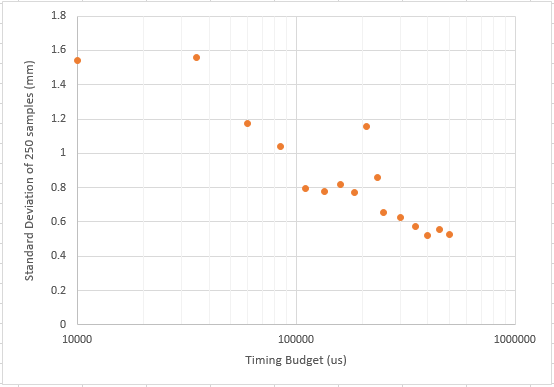
ST does not provide especially clear documentation of how those variables affect measurements, but I did not see a clear pattern here in my test configuration (using the sensor at a distance of about 160mm with a large white board), so perhaps they will not be very useful for your application, either. However, increasing Measurement Timing Budget seems like a reliable way to decrease variation of measurements. Here are standard deviations of a set of 250 single measurement samples using different measurement timing budgets.
As you can see, increasing the length of time of the measurements reliably decreases the variance of the measurements, however you are trading measurement time for accuracy in those situations. Averaging multiple measurements should also decrease the variance. In my somewhat ideal test setup (with a large, close, reflective object), it appears that (if the trend holds), it would take several seconds of averaging to get to 0.5mm repeatability reliably. I would expect a non-ideal situation to take longer,
you don’t need to say sorry nathanb. Actually I’m sorry for being a bit impatient.
I did exactly what you said in your code.
// set the return signal rate limit (default is 0.25 MCPS)
  sensor.setSignalRateLimit(0.25);
  // set laser pulse periods (defaults are 14 and 10 PCLKs)
  sensor.setVcselPulsePeriod(VL53L0X::VcselPeriodPreRange, 14);
  sensor.setVcselPulsePeriod(VL53L0X::VcselPeriodFinalRange, 10);
Are these values(0.25,14 & 10) to be set to another specific values? If yes, then to which values?
From the chart and as you said, I can see that higher the timing budget, lower the variations. How high should i set my timing budget? currently it’s set to 200 ms. Should I set it to 2000 ms?
I understand it would be at the cost of delay in time for measurement, but I don’t have time constraints. I don’t mind if the readings take more than 2 sec.
After doing some tests, is seems like changing the defaults does not increase the accuracy for most cases, but what range of distances are you trying to measure?
You might try 500ms and to double the number of measurements you are averaging, but again, your setup might vary. Also, it seems like the material does have a small effect on measurement range and that the average of a bunch of measurements does not always equal the true distance. It seems like it might not be very practical to get a range that is more accurate than a few millimeters. This other ongoing thread might be useful for you:
Thanks nathanb, I agree that changing the defaults doesn’t make much of a difference. I am trying to measure a range from 0 to 600 mm. I tried 500 ms and it gives consistent readings without much fluctuations, in fact when I add a median Filter it gives even better readings. I am posting my code below.
#include <Wire.h>
#include <VL53L0X.h>
#include <MedianFilter.h>

MedianFilter test(10, 0);
VL53L0X sensor;
float sum = 0;

float  sensorvalue = 0;


void setup()
{
  Serial.begin(115200);
  Wire.begin();

  sensor.init();
  sensor.setTimeout(500);

  // Start continuous back-to-back mode (take readings as
  // fast as possible).  To use continuous timed mode
  // instead, provide a desired inter-measurement period in
  // ms (e.g. sensor.startContinuous(100)).
  sensor.setMeasurementTimingBudget(200000);
  sensor.startContinuous();

  sensor.setSignalRateLimit(0.1); // 0.25 MCPS

  // sensor.setVcselPulsePeriod(VL53L0X::VcselPeriodPreRange, 18); // 14 and 10 PCLKs
  //sensor.setVcselPulsePeriod(VL53L0X::VcselPeriodFinalRange, 14);
}

void loop()
{


  int val = sensor.readRangeSingleMillimeters();
  test.in(val);
  val = test.out();
  Serial.print("val value = "); Serial.println(val);

  sum = 0;
  float  arrayofreadings[10];
  for (int i = 0; i < 10; i++)
  {
    int val = sensor.readRangeSingleMillimeters();
    test.in(val);
    val = test.out();
    arrayofreadings[i] = val;
    if (sensor.timeoutOccurred()) {
      Serial.println(" TIMEOUT");
    }
    sum = sum + arrayofreadings[i];
      Serial.print("sensor value = ");Serial.print(val); Serial.print("     ");
    Serial.print("sum value = ");Serial.println(sum);
  }

  sensorvalue = sum  / 10;
  //sensorvalue = measure.RangeMilliMeter;
  Serial.print("sensor value = ");
  Serial.println(sensorvalue);

}
But the problem with this code is that it is giving measurements that are quite far from the actual measurements.
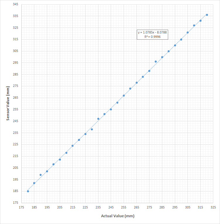
As you can see, the difference between actual value and sensor value keeps on increasing. But I can’t seem to find an equation that satisfies this variations. If there is some sort of mathematical curve that can predict the deviation of the sensor value from the actual value, then I can use it to correct the error.
I put your data into a spreadsheet and it looks like over that distance range and with the objects you are sensing, a simple linear relationship does a pretty good job:
I’d use a linear correction factor and also an EMA to smooth out fluctuations.
It works rather well.
However, as I found out in another thread, the sensor is not a digital caliper! You cannot expect the accuracy as if it were a Leica or Baumer device, costing from $300 upwards. The VL53L0X is a low-cost part for consumer electronics. And as such, the readings are influenced by ambient light, material the laser is bounced off, texture of the material the laser is bounced off and the colour of the material, too.
The VL53L1X may do a bit better, I ordered one from pololu.
Hi @Dhruvan and @nathanb
I noticed that in your post on July 21st, the code you posted shows you reduced the signal rate limit down from the default of 0.25, see this line: sensor.setSignalRateLimit(0.1); // 0.25 MCPS
Perhaps this is influencing your accuracy.
When I did that testing, I compared sets of 1000 measurements at a few distances from 63 to 333mm from the sensor using 0.05 and then 0.75 for that value. Changing the value made a difference, but generally less than 1mm on average under otherwise identical conditions and there wasn’t really a clear trend at different distances.
Nathan,
I’ve experimented with increasing the sensor.setSignalRateLimit value up to 5.00 and higher in my setup, and it seems to reduce the variation significantly. If you increase it beyond 5.75 it seems to stop reading reliably. (in my case at least)
I also found lowering the VCSEL periods to their minimum helped with increasing repeatability.
Note: My setup is in a pretty controlled environment with ranges under 0.5m so I can’t speak to every case.
Thanks, I cam a bit late in the discussion. What I need is already here. So no need to ask question. Just saying thanks to all who posted and supported.