


Thanks Kevin I should have been clearer.
I did have the connector at the Wixel on P0_0 and P0_1 this has been corrected.
Now the yellow wire is Z and connected to P0_1 and green wire is X and connected to P0_2.
The Ohm meter reads short from Gyro pins at the board to Wixel pins at the board with out USB connection for both X and Z pins. All pins and solder joints have been inspected and metered. I get 3.28v at the vin to gnd on the gyro.
I will run another set of tests tonight and post results.
When I first got the gyro I tested it on the Maestro with the gyro in my hand, using a different cable harness, just to move two servos based on gyro X and Z values as a crude quick test. While it did work it was not consistent. Not always moving the servo on gyro movement. I thought that it was the lack of code depth in the stack oriented Maestro and my project expects the gyro to communicate with the Wixel so I moved to the C platform and more complex code with diagnostics. This was when I confirmed something was not as per my expectation.
The mistake in the connection does not explain the difference between expected data and actual.
To recap the gyro is moving in a flat plane on the Z axis. Riding on top of a servo wheel that is controlled by the Maestro a simple script moves the servo at full speed to the right pauses 500 delay then to left pauses 500 delay and repeats.
How would the expected result from this test harness appear as a graph?
I am expecting something like the red line.
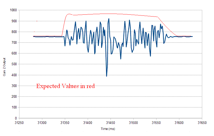
My crude timing estimate is less than one second to move and delay, we know the delay. I predicted that this standard servo at full speed would cover 3/4 of its range in less than 350 ms. The graph does suggest about about 300 ms of movement.
James