I’m trying to make a moving installation - three linear actuators driving the petals of three plexi flowers to open and close - and am having trouble working with the 18v7 that I’m trying to hook up to the arduino.
So - my setup is
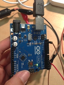
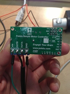
one generic linear actuator hooked up to the 18v7 motor controller that is powered by a 12V ACDC power supply. And I connected the pins 3 and 4 of the arduino to the rx and tx of the motor controller.
It all seemed to work fine, except I was getting an error LED on the motor controller.
When I disconnected the arduino and hooked the motor controller to the computer via USB, i kept getting an error message from the Pololu Motor Control Center. It first said that it couldn’t find the USB kill switch, and now it says there is an error getting the firmware version to the device. However, the red light still blinks and the green one too.
Please help! I need the arduino to drive the linear actuator back and forth a couple of times. I also upgraded to Win 8 if you think that might cause issue. I have already tried to
change USB ports
Restart computer
Disabled Digital Signature
nothing works… hope you can help! the installation is up for review on Monday - would appreciate any advice you might have.
I have been helping ttan over the phone and I would like to provide some context for anyone who is following this thread. The first time she set up this system (12V DC + Arduino Uno + SMC18v7 + generic linear actuator from Pololu), I forget how well she got it to work but then at some point the SMC stopped working while she was reading the manual. That was a few weeks ago. A second Simple Motor Controller died today while we were on the phone, and that is probably because she accidentally plugged the 12V power supply (12V 3A wall power adapter) into the OUTA and OUTB pins of the SMC. The board still kind of worked after that; it was recognized by the computer but she got a lot of errors when she tried to use the USB connection. She has exactly three more unopened Simple Motor Controllers so she should be able to finish the project this weekend as long as none of them break. I encouraged her to post some photos on the forum so we can see if there is anything wrong before she tries to get the system working again. She has just been using the simplest Arduino example code we provide in the “Arduino Examples” section of the Simple Motor Controller User’s Guide.
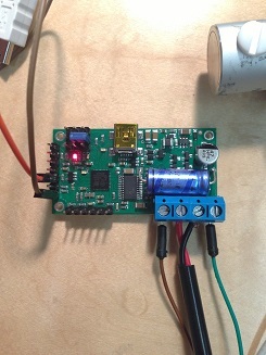
Thank you for the pictures. I don’t see anything seriously wrong, but I do think the weak point of this setup is the connection of the 12V power supply. I can’t see all the connections, but it looks like power is coming from the 12V adapter to an alligator clip, and then to at least one other type of wire before going to the Simple Motor Controller. You should try to plug the adapter directly into the Simple Motor Controller if possible, but it looks like the wires from the adapter might be too short for that.
I’m sure she would appreciate input from other forum members as well.
thanks David. I tried the same setup with a fresh motor controller and a different computer, but still had no luck… again, it looked as if the motor controller and arduino are receiving the signals, but the actuator isn’t responding…
What are the three LEDs on the Simple Motor Controller doing? Could you post a screenshot of the Status tab of the Simple Motor Control Center so we can get an idea of what is going wrong?
Are you able to control the actuator over USB instead of with the Arduino, by using the input in the Status tab?
If you hook the 12V power straight to the inputs of the actuator, does the actuator move?
If you don’t have the actuator hooked up, but only the simple motor controller and the Arduino, do you see a voltage on the outa/b port? You will need a multimeter to measure this.
If you don’t have a multimeter, find the nearest Radio Shack and get their cheapest version, it’s probably good enough to detect presence/absence of voltage. If you don’t know how to use it, you typically turn it to “voltage” and a range that includes the voltage you want to measure (e g range 20V or 50V) and then connect the measurement probes to what you want to measure. Try it on the 12V power supply first to make sure you got it right!