Brand new to this board so this is, I’m sure, a user problem. Is the Configurator supposed to work with TTL signals as well as COM? If so, it is OK with 3.3V TTL rather than 5V?
Thus far I am unable to get things set correctly so that the configurator finds the TReX. Any tips will be greatly appreciated.
Yes, the TReX Jr configurator program works with TTL serial and it can work with 3.3V signals, though there is very little room for noise on the serial input when operating at this voltage (the TReX Jr is guaranteed to interpret anything over 3V as high) and the serial output from the TReX Jr will be at 5V, so you need to make sure your USB-to-serial converter has a 5V-tolerant serial input or take steps to protect it (such as a voltage divider).
What are you using as your USB-to-serial converter? Are you sure you’re trying to connect to the right COM port? Are you using a baud rate of 19.2 kbps? Do you have a common ground between your USB-to-serial converter and the TReX Jr?
I am unable to get the Configurator to find the TReX Jr. board.
Here’s what I am doing, exactly.
I follow these directions from page 21 of the User’s Guide:
1. Turn off power to your TReX Jr.
2. Put the TReX Jr into Serial Mode by removing the Mode jumper.
3. Ground the TTL Serial Out (SO) pin by attaching the Learning-Mode/Firmware-Upgrade jumper.
4. Attach the Mix jumper.
5. Restore power to the TReX Jr; the status LEDs should alternately flash red and green.
6. Remove the Mix jumper; the status LEDs should alternate faster.
7. Remove the Learning-Mode/Firmware-Upgrade jumper; the green status LED should now briefly flash
every second.
8. Reconnect your TReX Jr’s serial cable to establish a connection between your TReX Jr and your computer.
I have tried using a USB to TTL cable from FTDI; the documentation for it is here:
on my system this cable enumerates to COM12. I have COM12 set to 19,200 8N1. I am using the Yellow, Orange, and Black wires and connecting the cable to the TTL pins plus GND on the TReX Jr. No success. BTW, I use this cabel to “talk” to my Arduino chips all the time without any issues.
I have also tried a serial cable connector to COM1 on the computer. I have COM1 to 19,200 8N1. I am using pins 2, 3 and 5 of the cable to connect to the COM pins on the TReX Jr. Also, no success.
In both cases I have switched the TX/RX wires just on the chance that I have them backwards.
I’m a little confused. Are you trying to get the TReX configurator to talk to the TReX Jr in a way that lets you configure and test the device, or are you trying to update the TReX Jr’s firmware? If it’s the former, you shouldn’t be performing the firmware-update sequence on page 21. If your board is new, you shouldn’t need to perform a firmware upgrade.
The COM port settings on your computer don’t affect the baud rate. Rather, the baud rate is set by the device creating the virtual COM port (your FTDI board in this case) in response to commands from the software that opens the COM port.
In general, making trial-and-error connections is a very bad practice. By swapping the wires, you were connecting one output directly to another and shorting two different voltages together when you attempted to send serial data, which could burn out the pin on your FTDI and/or the TReX Jr.
Thanks for the reply. I am not including the paragraphs here for the sake of brevity but on Page 21 of the User’s Guide it states that, “The firmware that comes preloaded on every TReX Jr motor controller is
trexjrv1_0.trx [pololu.com/file/download/trexjrv1_0.trx?file_id=0J91] (137k trx).” It also states, “Our most recently released firmware update for the TReX Jr motor controller is
trexjrv1_2.trx [pololu.com/file/download/trexjrv1_2.trx?file_id=0J238] (161k trx) (version 1.2).” This would lead one to beleive that one neeeds to update the firmware on every new TReX Jr.
Yes, my initial purpose was to get the firmware upgraded but that did not succeed as I was unable to recognize the board. But, asssuming I don’t need to upgrade the firmware I still need to talk to the board and your response didn’t tell me where I am going wrong. What do I need to do to recognize the TReX Jr. board?
Recent units have been shipping with the newest (v1.2) firmware, so your device probably already has it. I would recommend checking the firmware version using the configurator before trying to perform a firmware update. Note that the user’s guide also says:
[quote]All other supported baud rates work properly in firmware versions 1.0 and 1.1, so if your TReX Jr does not have version
1.2 firmware and you do not need communicate serially at 38,400 or 28,800 bps, you do not need to update your firmware to 1.2.[/quote]
We don’t recommend you update the firmware unless you have the older version and need to communicate at a baud rate of 38.4 or 28.8 kbps.
First, does your TReX Jr still do its normal startup sequence when you apply power? Specifically, do you see the LEDs flash when you first apply power in the way described in the manual, or do you see no sign of life at all. The first stage of the firmware update procedure is to erase the existing firmware, so I want to make sure you still have the old firmware running on the device. If the old firmware has been erased, you will need to perform a firmware update before you can interface with it using the configurator.
To connect to the TReX Jr with the configurator, you just need to make the appropriate serial connection (FTDI transmit to TReX Jr SI pin, FTDI receive to TReX Jr SO pin, and FTDI ground to TReX Jr ground) and click the “Connect to TReX” button. This will bring up a window that lets you specify the COM port of your FTDI, the baud rate (this should be 19.2kbps), and error checking (this should be “none”). If you do this and click OK, what happens? Note that the TReX Jr must be powered, and you should not do the firmware upgrade sequence prior to making the serial connection.
To perform a firmware update, you need to carry out the sequence you described in your previous post and then press the “Upgrade Firmware” button. Is this what you did? If so, can you tell me at what point and how the firmware upgrade procedure failed? What message did you get?
I get the normal red & green LEDs flashing every second or so. This is what it did out of the box. If I power the device down and disconnect the SO to GND jumper and connect the TTL cable as you describe then power the unit back up the red LED flashes about 5 times and then the green LED flashing rapidly. I have the Configurator set to COM12, Baud 19,200, Error Checking none, Stop bits one, Use expanded protocol is unchecked. I get the message, “Could not detect a TReX motor controller on port COM12.” This is the same message i have gotten with every attempt since I began this process yesterday.
I have taken no other steps toward changing jumpers as was described in the upgrade process. In other words, I started with the board the way it cam out of the box. The only board-level change I made was to pull the jumper off the SO to GND pins and connect the TTL cable.
Okay, let’s briefly try something else. Can you install the Pololu serial transmitter utility and try using it to communicate with your TReX Jr using the same connection board connections described in your previous post? The serial transmitter utility lets you send individual bytes and reports any bytes received, so it will let us see better what is going on. Try sending the byte 0x81. Do you get anything back from the TReX? What if you send 0x82 or 0x83? If you send the two-byte command {0xF0, 0x7F}, do you see the yellow M3 (aux motor) LED turn on?
One thing I forgot to mention is that you need to have the TReX Jr in serial mode for this last command to have any effect. To put the TReX Jr into serial mode, disconnect power from the TReX Jr, remove the mode-selection jumper, and reapply power. Now when the device starts up, you should see the red LED blink five times and then remain solidly on.
In serial mode, can you also try just sending the single byte 0xF0. If things are working normally, you should see the green LED turn on and stay on. If you do not see this, can you pay close attention to the green status LED and see if you see it briefly flash at all when you send serial data?
I do have the red LED lit solid. I tried the other commands and got no received data back. I tired F0 and got no additional lights: green LED is dark. I do get a few random characters received when I power the board down.
I closed the Transmitter and restarted it just to be sure it hadn’t lost it’s mind when I shut down the TReX to pull serial mode jumper and that made no difference.
Just to make sure, you set the baud rate field at the top of the serial transmitter window to 19200, right? Is it possible for you to send me a photo of your setup? If you disconnect your FTDI from the TReX Jr and instead connect your FTDI’s transmit pin to its receive pin, do you receive get a response with the serial transmitter when you send a byte? Also, how are you powering your TReX Jr?
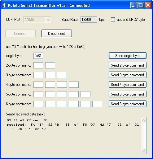
It’s very unlikely, but what you’re seeing could happen if the board’s serial settings have accidentally been changed. One other thing you could try is resetting the serial parameters. When you transmit 0x81, you should see the following in the serial transmitter:
Is that screen capture showing what you see when you connect your FTDI transmit directly to the FTDI receive (i.e. no TReX Jr in the system)? Can you post a picture of your setup and tell me how you’re powering your system?
Sorry, my bad. I still had the transmitter connected when I tested the Configurator. Once I disconnected the transmitter I am now able to connect. Thank you very much.