This is a little off Pololu topic, but it’s been driving me nuts and I’m hoping some one can help.
I’ve been using online circuit guides to help me make something using a 555 timers. The idea was to incorporate a pot to vary the time delay. For my R1 I’m using 3MOhm resisters + 1MOhm Pot. My R2 = 3 kOhm. and My C = 1000 uF capacitor. And my power source is a 9Volt battery; I’m trying to power a small dc motor I took out of a playstation controller. I used some programs and calculators online to get these values and on my test solderless breadboard I could adjust the pot and get breaks varying between 30 seconds, to 7 minutes in between 4 second ON times. Which is exactly what I wanted. Once I soldered everything together and started leaving it on, it now goes on for the 4 seconds and off for 3, then on again, no matter what I do. I re soldered the whole thing twice, and it starts fine and then some time later it reverts to this 3-4-3-4 second loop, regardless of pot position.
Any ideas?
Can you post your schematic or pictures of how you wired things up?
-Adam
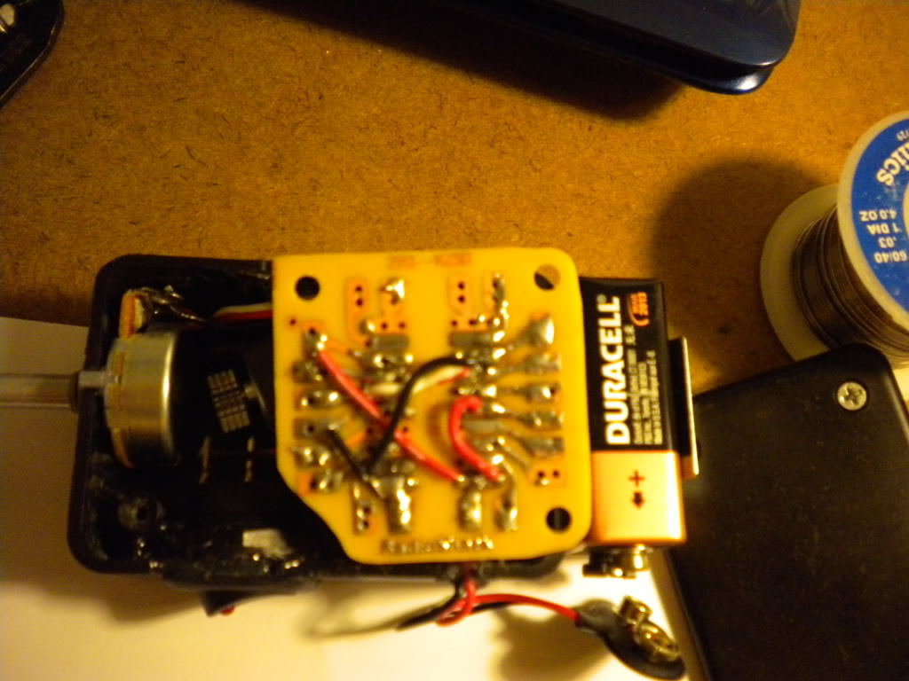
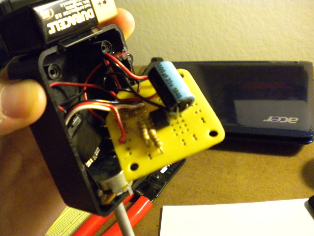
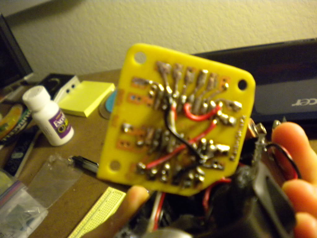
The top two are two astable schematics that I used as guides. They are both the same just with different layouts. The third is a MSpaint schematic that matches what was soldered to the board. The rest just show pictures of the board. The 1M Ohm resisters are rated for 1/4 watts while the 1.5 kOhm resistors are rated for 1/2 watts. I didn’t think it would make a difference and that’s all Radioshack had in stock for those sizes at the time.
I have the pot input at pin 8 and output heading towards pin 7 with 3 MOhm in between output and pin 7. I’ve switch up the setup a couple times with no avail. Does the order of the resistors going before or after the pot matter?
Thanks for posting the schematics, it makes things much clearer.
For astable operation, pin 5 should be connected through a capacitor (0.1uF) to ground. In your schematic you have it connected directly to ground. If you don’t have a 0.1uF capacitor handy, try leaving pin 5 completely disconnected.
Other than that your circuit looks fine, and the order of resistors in series makes no difference. With your component values it looks like your motor should have an on time of about 2 seconds, and an off time adjustable between 34 and 46 minutes.
-Adam
The linear pot I’m using is kicking back some bizarre behavior. I still get a minimum time of around 30 seconds closer to the 180 degree mark on the pot I get intermittent breaks between 5 minutes to 3 minutes. and past that I get no reaction. I’ve left that thing on for close to an hour and have had no response. Is there a general threshold for pots where I would incur a dead area of no response? I didn’t think there really .
I’ve seen some pots where the wiper can move past the resistive strip near the extremes of its range, but you shouldn’t be having trouble with it in the middle. There might just be crud in it, can you check the resistance with a multimeter when you get it in one of these non-responsive areas?
-Adam
I’d have to buy one, or borrow one. Not having one is a crime, I know. I’ll see what I can do tomorrow.