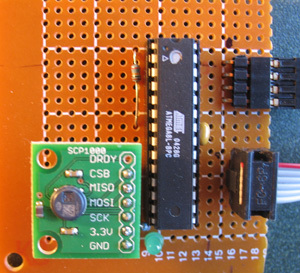
SPI and LCD with Orangutan

I have a small SPI device (a pressure sensor actually) we’re considering using in one of our projects that I need to demo next week, and it would be really cool to plug it into the programming header of the Orangutan and have it read out on the LCD.

In this case cool means small, self-contained, and not involving a breadboard and a laptop.

I was all happy to try this until I got out my Orangutan schematic and saw that the SPI lines are all shared with the LCD. I never bothered to learn the real guts of how the LCD works, I just grabbed the various libraries people here have come up with.

SO, my question is, how horrendous would it be to alternate between polling an SPI device and updating the Orangutan LCD? Could I just run lcd_init() and spi_init() every time I want to do one or the other and let them duke it out?

I currently have the devices SS line permanently held low, but I could switch that to an IO line if it would help. Basically, if I can get it done tomorrow it’s worth it, and if not it’s breadboard and laptop time!

-Adam

Hi, Adam.

The SPI lines on the Orangutan are used as LCD data lines, so I would expect that the LCD will be unaffected by SPI communications as long as you’re not using the LCD control lines. You just need to make sure you don’t try to send the LCD a command in the middle of an SPI transmission.

My initial thought is that it might be sufficient to simply disable the the Orangutan’s SPI every time you want to update the LCD and enable the SPI every time you want to communicate with your pressure sensor. Enabling the SPI in master mode will override the functionality of the IO lines; disabling the SPI should restore them.

I envision your using the pressure sensor as a slave with its slave select tied to one of the Orangutan’s IO lines. This way, whenever you are updating the LCD, you can drive your sensor’s SS high to disable its SPI and keep it from treating the activity on the lines as an SPI communication.

I’ve never tried using SPI on the Orangutan, but at first thought it seems like it’d be straightforward.

- Ben

Hey, Adam, glad to see you’re considering this! I saw that about the Orangutan, and wondered about plugging straight into the ISP header. Never tried it, though.

Rather than letting them duke it out, my guess is the LCD would work happily with SPI going full blast, just as Ben said, so long as you weren’t hitting the enable pin on the LCD. It just wouldn’t care.

As far as driving the LCD without affecting the SPI hardware, yeah, having !SS tied to an I/O line would do it. When you’re writing to the LCD, just don’t enable !SS to your device.

Another route to go would be to disable the SPI hardware when the LCD is being written to, as Ben said, and re-enable it when you want to talk to your device. There’s nothing in the library to do that YET, but if your test works out I want to play, too, and will happily add spi_disable(). In the meanwhile, you can toss this in when you want the SPI stuff to stop:

SPCR &= ~( 1 << SPE ); DDRB |= ( 1 << PB4 );

That should turn off the enable bit for SPI on the Orangutan and Baby-O and set up PB4 (MISO) as an output. To turn it back on you can do:

SPCR |= ( 1 << SPE ); DDRB &= ~( 1 << PB4 );

A couple of other bits get set in spi_init(), but most of it is making sure all the I/O lines have their registers set up to point the right way. Since the LCD wants them all as outputs and SPI wants all but PB4 as outputs, too, aside from re-enabling SPI, that one I/O change should be all you need to do.

But now I have to ask:

What sensor are you using? How fast can it pick up a change? I’m guessing it’s a barometric pressure sensor for picking up altitude? I’m working on a flight computer for model rockets, and have been poking around at various options for reading pressure. I’d be very VERY interested to hear what you’re doing, and how well it works out.

Tom

I’m playing with this evaluation board from Sparkfun. It’s a MEMS absolute pressure and temperature sensor, used for relative altitude changes, weather prediction, think something for a fancy digital watch or mountain-bike computer. They claim it can detect the pressure change with as little as a 9cm change in height. I’m guessing the change will need to be greater than that to overcome noise, but we’ll see. You can ignore the temperature data for small/indoor altitude changes, and they have some huge formulas to take it into account for estimated sea-level altitude and such.

Actually I’m kicking myself for not getting the I2C version. It would be easier to connect the 3.3V device to 5V logic, and the PC104 computer that I’ll eventually have to hook it up to has an I2C interface.

The device itself is supposedly difficult to solder without damaging, and Sparkfun’s evaluation board only comes with the SPI version of the chip. A little digging (after ordering two from Sparkfun) and it tuns out VTI sells either version on a similarly sized and priced (~$50) evaluation board through Digikey.

Anyway, I’ll let you know how it works, and maybe I’ll throw the SPI spares in my own model rockets. I don’t know if you’ve ever tried the Estes Max Trax with the drop-timer altimeter, but it’s really lame!

-Adam

Never did. My only serious foray into model rocketry was water rockets, which is what I’m aiming this at. Less of an issue here, but when I started doing rockets in Texas, it was a lot easier to launch water rockets in the summer than pyro rockets because of droughts and burning bans. Soaking the grass is almost always ok.

But that also makes the flight computer a lot more complicated to pull off. I’m after barometric pressure for altitude, Z axis accelerometer in the 80g to 100g range, X and Y axis accelerometer in the 5g range (oscillation), a 150PSI pressure sensor for the rocket’s pressure vessel, potentially a third pressure sensor with a pitot tube to pick up airspeed… the list is uncomfortably long. Throw in an SPI flash chip from Atmel, and it can store gobs of data very very quickly.

Right now I’m leaning toward some analog sensors and either an I2C or an SPI 16-bit ADC for the two low pressure sensors. (Chamber pressure can be done on the AVR’s 10-bit ADCs.) But that starts to take up a lot of real estate on the board at that point. That sensor you’re using looks nice and small.

But I digress a lot. Let me know how your testing goes.

Tom

Adam, I checked in a new version of lcd.c that saves the SPCR register, disables the SPI interface for LCD writes, and restores the register afterward. This should let you mix LCD and SPI code transparently on the Orangutan.

I still haven’t tested this yet, but it will be before 0.4 is released.

Tom

Hey Tom,

I’m working out the bugs in this code, and I think it’s going to work, but I discovered something I thought you would want to know about (maybe you already do).

I can’t twiddle just the SPI enable bit, because when you clear it, it also clears the SPI master and SPI clock bits. Also, setting the SPI enable and SPI master bits takes over the function of the MISO pin, and relinquishes it when SPI enable is cleared, so you don’t have to do that manually.

I’ll post my whole code when it works!

-Adam

Sweet! Thanks for the info, Adam. I’m hoping to play with this some this weekend, too.

The way I’m saving the SPI registers and restoring them should take care of the SPI master and SPI clock bits as well (basically it stores the state of that register, dinks it the way it needs, then dumps the stored version back into the register.) But it’s something to test thoroughly.

Cool! I’m glad SPI through the ISP port works. I was hopeful.

Tom

Yeah, I was REALLY tempted to repurpose the reset pin as my SS pin to keep it all in the 6 pin header. Probably better to tackle one challenge at a time, plus I need a seventh line for a data-ready interrupt.

Just had my first successful transmission of packets to the sensor!

-Adam

Yaaaaay! Ok, that cinches it: I’m playing with this tonight.

Tom

…and it’s totally awesome! Actually, it worked last night, but I didn’t get around to posting it. I struggled for a few hours before realizing that I had neglected a pull-down resistor for the MISO line, which I put a protection diode on for when the LCD was running. I even missed it looking with an osciliscope, since I connected it to the anode side of the diode. Anyway, here’s the overly long single file code:

/*SCP1000 Pressure Sensor SPI Test for Atmega8 Orangutan
Adam Borrell
Mobile Robotics Lab
University of Michigan
6/30/07*/

#define LCD_Clear 0x01
#define LCD_Line1 0x80
#define LCD_Line2 0xC0
#define F_CPU 8000000UL 
#include <avr/io.h>
#include <util/delay.h>

void SPI_MasterPreInit();
void pressureInit();
void pressureWrite(unsigned char addr, unsigned char data);
int pressureRead16(unsigned char addr);

void LCDInit(void);
void LCDSendData(unsigned char data);
void LCDSendCommand(unsigned char command);
void LCDPrintString(const unsigned char *string);
void LCDGotoXY(unsigned char x,unsigned char y);

int main(){
	unsigned char buf[8];
	int i,j=0;

	DDRD|=(1<<PD1);//set LED pin to output
	PORTD|=(1<<PD1);//turn on LED

	SPI_MasterPreInit();
	pressureInit();

	LCDInit();

	while(1){
		if(PINC&(1<<PC4)){//new data ready
			PORTD^=(1<<PD1);//toggle LED

			SPCR=(1<<SPE)|(1<<MSTR)|(1<<CPHA)|(1<<CPOL)|(1<<SPR0);//Enable SPI (takes over MISO function), Master, set clock rate fck/16 (500KHz)
			itoa(pressureRead16(0x20),buf,10);
			SPCR&=!(1<<SPE);//Disable SPI (releases MISO function)

			LCDSendCommand(LCD_Clear);
			LCDSendCommand(LCD_Line1);
			LCDPrintString(buf);
			itoa(++j,buf,10);
			LCDSendCommand(LCD_Line2);
			LCDPrintString(buf);
		}
	}
	return 0;
}

void SPI_MasterPreInit(){//initialize SPI without enabling/compromising LCD pins
	PORTC|=(1<<PC5);//bring PC5 high first
	DDRC|=(1<<PC5);//Set PC5 (my chosen SS) to output
	DDRC&=~(1<<PC4);//Set PC4 (Data Ready Interrupt) to input
	DDRB|=(1<<PB2)|(1<<PB3)|(1<<PB5);//Set SS (must be output or externally brought high), MOSI and SCK output, all others user defined
}


void pressureInit(){
	int i;
	for(i=0;i<5;i++){
		_delay_ms(20);//startup delay
	}
	SPCR=(1<<SPE)|(1<<MSTR)|(1<<CPHA)|(1<<CPOL)|(1<<SPR0);//Enable SPI (takes over MISO function), Master, set clock rate fck/16 (500KHz)
	pressureWrite(0x02,0x2D);//Configure SCP1000 with low noise configuration
	pressureWrite(0x01,0x03);
	pressureWrite(0x03,0x02);
	for(i=0;i<5;i++){
		_delay_ms(20);
	}
	pressureWrite(0x03,0x0A);//Select High Resolution Mode
	SPCR&=!(1<<SPE);//Disable SPI (releases MISO function)
}

void pressureWrite(unsigned char addr, unsigned char data){
	PORTC&=!(1<<PC5);//bring SS Low

	SPDR=((addr<<2)|(1<<1));//Transmit shifted address with write bit
	while(!(SPSR&(1<<SPIF)));//Wait for transmission complete

	SPDR=data;//transmit data
	while(!(SPSR&(1<<SPIF)));//Wait for transmission complete

	PORTC|=(1<<PC5);//bring SS high
}

int pressureRead16(unsigned char addr){
	int data=0;

	PORTC&=!(1<<PC5);//bring SS Low

	SPDR=(addr<<2);//Transmit shifted address with read bit
	while(!(SPSR&(1<<SPIF)));//Wait for transmission complete

	SPDR=0x00;//transmit blank data to generate clock ticks
	while(!(SPSR&(1<<SPIF)));//Wait for transmission complete
	data=(SPDR<<8);//grab bits

	SPDR=0x00;//transmit blank data to generate clock ticks
	while(!(SPSR&(1<<SPIF)));//Wait for transmission complete
	data|=SPDR;//grab bits

	PORTC|=(1<<PC5);//bring SS high

	return data;
}

/*
Send lower 4 bits of data byte to display
*/
void LCDSendNibble(unsigned char data){
	data&=0x0F;				//lower 4 bits of data
	data<<=3;
	PORTB&=~0x38;			//clear LCD bus bits 456
	PORTB|=(data & 0x38);	//or in data
	data<<=1;
	PORTD&=~0x80;			//same for top bit on PORTD.7
	PORTD|=(data & 0x80);
	_delay_us(1);
	PORTD|=(1<<4);			//E = 1
	_delay_us(2);			//required minimum 1 us delay
	PORTD &= ~(1<<4);		//E = 0
	_delay_us(1);
}

/*
Send a character to the LCD display
*/
void LCDSendData(unsigned char data){
	PORTD&=~(1<<3);	//R/W =0
	PORTD|=(1<<2);	//RS = 1;
	LCDSendNibble(data>>4);
	LCDSendNibble(data);
	_delay_us(100);	//38 us typically needed to complete this action
}

/*
Send a command to display. Required delay time depends on the command and the 
LCD controller clock frequency -- here assumed to be the minimum 190 kHz
*/
void LCDSendCommand(unsigned char command){
	PORTD&=~(3<<2);			// R/W=0, RS = 0;
	LCDSendNibble(command>>4);
	LCDSendNibble(command);
	_delay_ms(3);			//maximum required is 2.1 ms for "clear display"
}

// print a string constant
void LCDPrintString(const unsigned char *str){
    while(*str!=0)LCDSendData(*str++);
}

// set print position to (x,y) where y=line number (0 or 1), x = character position 0, 1, etc.
void LCDGotoXY(unsigned char x, unsigned char y){
	volatile unsigned char ddram_addr;
	ddram_addr=0x80;			//initialize data ram address to 0 (default)
	if(y==1)ddram_addr=0xC0;  	//start print at line 2, DDRAM address 0x40
	LCDSendCommand(ddram_addr+(x&0x7F));
}

/*
Initialize the LCD Display, timing requirements taken from datasheet
Set PORTB.3,4,5 to DB 4,5,6
Set PORTD.2,3,4,7 to RS, R/W, E and DB7
Send required start-up sequence to set 4 bit interface, 2 lines, 5x8 characters and clear display
*/
void LCDInit(void){
	DDRB|=(7<<3);
	DDRD|=(1<<7)|(7<<2);
	PORTD&=~(7<<2);			// E=0,R/W=0, RS = 0;
	_delay_ms(20);			//required startup sequence from power-on (see datasheet)
	LCDSendNibble(0x03);	//set interface=8 bits
	_delay_ms(10);			//wait at least 5 ms	
	LCDSendNibble(0x03);	//set interface=8 bits
	_delay_ms(1);			//wait at least 100 us
	LCDSendNibble(0x03);	//set interface=8 bits
	_delay_ms(1);			//wait at least 100 us
	LCDSendNibble(0x02);	//set interface=4 bits
	_delay_ms(1);			//delays after this are built into SendCommand
	LCDSendCommand(0x28);	//set interface=4 bits, 2 lines, 5x8 characters
	LCDSendCommand(0x08);	//display off, cursor off, blink off 
	LCDSendCommand(0x01);	//clear display
	LCDSendCommand(0x06);	//entry mode set, cursor shifts right after character rcvd.
	LCDSendCommand(0x0D);	//0b01DCB  D=1:Display on, C=1:cursor on, B=1:Blink on
}

-Adam

SWEEEET!

I didn’t get to play with it any last night, but I sure hope I get to try this out today.

Tom

Yeah, this looks soooooooooo much cleaner than the usual laptop and breadboard setup to test something new, not to mention less cumbersome to carry up and down stairs while I take readings!

Tom, the sensor turns out to be pretty noisy, or maybe its super accurate and picking up air pressure fluctuations in my office. Anyway, the 9cm claim is a joke, but with averaging I’m guessing I could get within a meter or so.

-Adam

I’ve been having fun with the SCP1000 pressure sensor as well. However, I read that the earlier versions (revision A) had problems with the SPI interface, and would lock up the port–conflicting with the programmer. For that reason I chose to go with a separate controller using an Atmega8 and adopted the bit-banged SPI interface posted by the Nathan Seidel at SparkFun.

The bit-banged SPI routines work well and have the advantage that they can use any set of pins. It would be trivial to adapt them to the O, then you could have two completely independent SPI ports.

I’m using an FTDI USB-rs232 converter to power the board and transfer the readout to a PC, although shortly I’ll make it self contained, with a small graphic display. Would there be interest to adapt this to the Orangutan?

I ran into some problems with the chip that led to serious errors and noise, which was verified to be due to eeprom checksum error on startup. The fix was to reinitialize after startup. Also, you need to explicitly set low noise and high resolution mode. It appears that as an altimeter, suitable averaging gives about 1 foot altitude resolution!

Startup code:

    printf("\nPressure Firmware v1.0");
	Delay_ms(60);

// startup error checking

	for(i=1; i<7; i++) {
	x = read_register(0x07);			//STATUS register
	if ((x&1)==0) break;				//successful if LSB=0
	Delay_ms(10);
	}

// reinitialize to fix checksum error

	//write_register(place, thing)
	write_register(0x06, 0x01);			//write 1 to RSTR (software reset)
	Delay_ms(60);

	for(i=1; i<7; i++) {
	x = read_register(0x07);				//STATUS register
	if ((x&1)==0) break;
	Delay_ms(10);
	}
	x = read_register(0x1F);				//DATARD8 register
	if (x==1) puts("-OK"); else	puts("-Startup failure!");		//should equal 1 if eeprom checksum OK
   
    //Configure SCP1000 with low noise configuration
    //=====================================
    //write_register(place, thing)
    write_register(0x02, 0x2D);
    write_register(0x01, 0x03);
    write_register(0x03, 0x02);
    
    Delay_ms(100);

    //Select High Resolution Mode
    write_register(0x03, 0x0A);
    //=====================================

Complete code may be downloaded from
uoxray.uoregon.edu/orangutan/scp1000.c

Cheers, Jim

Adam:

In looking at your SCP1000 code, I think I see one reason for the excessive noise.

The ADC in the SCP1000 is 19 bits, but only the top 17 are considered valid. You need to read all 19, though, and shift right two to get a 17 bit pressure reading (in Pascals).

One way to do this is to read register 0x1F to get the top 3 bits, read register 0x20 to get the next 16, OR to make a 32 bit variable and shift this right by 2.

It is also possible that power supply noise is an issue. There have been discussions on this in the Spark Fun projects forum.

Jim

void scp_read(void)
{
    long temp_data;

    //Wait for new data
    while(1)
    {
     temp_data = read_register(0x07); //Check the status register for bit 6 to go high
     if (temp_data & 32) break;
    }

    temperature = read_register16(0x21); //Read the temperature data
    temp_data = read_register(0x1F); //Read MSB pressure data - 3 lower bits
    pressure = read_register16(0x20);

    temperature /= 2; //This is (temp * 10) / 20 so that the answer of 27.9 comes out as 279 (easier to print)
    temp_data <<= 16; //Shift it
    pressure = temp_data | pressure;
    pressure >>= 2;
}

Thanks Jim!

I have integrated the startup state checking you suggested, and my sensor seems to be fine (passes the checksum and status tests the first time). I guess I was just hoping (as we all do) for a more perfect sensor. I think this one is going to work out for us though.

Thanks for the code for reading the whole absolute pressure too, I’ll add that in at some point. I decided to read just the lower 16 bits to start so I could use the standard itoa function for displaying the output on the Orangutan’s LCD screen. Also, that’s the only register you have to read to reset the data ready interrupt line.

In our application we’re only interested in relative altitude change, and my office building has had a convenient air pressure since the weekend where only the lower 11 or 12 bits change over the (four) floors!

-Adam

Well, keep in mind that the bottom two bits are just noise!

Cheers, Jim