Something new for the maestro range

I’ve been researching various methods/products to deliver a PPM signal for a certain project im working on (http://fpvlab.com/forums/showthread.php?35491-DIY-hand-held-ground-station-help-needed-with-some-switches. and http://openrcforums.com/forum/viewtopic.php?f=45&t=6600&sid=2cfb1ce041115eda899aef60261e40c5)

Basically I want to build an all in one drone control station. I’ll use 6 pots (2 joysticks [x+y] + 2 sliders), and 10 switches/encoders for different mode selections and wot-not, and I will also likely have another 2 pots from a playstation thumbstick. There will be an ubuntu computer in the station as well, running the drone control software. The drone software will interface with a telemetry module, while I plan to have the pots/switches etc have there outputs eventually going through a seperate RC transmitter module. I want to keep these transmissions seperate to allow for a failure or redundency.
It will all be powered by it’s own NiMh battery, with the required stepped down voltages, so if I need to power the maestros with 5V, I can.

From all of my potentially 18 analog inputs, I will generate 8 PWM/servo signals, selectable/configured in the Ubuntu environment using the pololu software and scripts.
Im thinking I will need to use 3 Mini Maestro 12’s. 2 of them for the analog inputs and the last one to handle the PWM/servo signals. My input configuration requires 26 pins, where the maestros will have a total of 36 pins, so there will be room for expansion if/when required.
I want to be able to run the 3 Maestros independently from the Ubuntu computer, only using the computer to monitor, change and manipulate the settings as required. If the computer fails for what ever reason, I want to still have the Maestros working. The Maestros will be connected to the computer all the time and never disconnected.
The computer will be running the control software of a drone, and will have a touch screen interface, so I hope the provided software will work with touch controls. (for information, the computer i’ll likely be using is an Odroid U3, SBC)

Once I get this running nicely, I will look to develop some new software specifically for this application, to give better functions more suited to my purpose.

I know there is already lots of code in Arduino to do something like this, but it just doesn’t quite fit what im trying to do. Anyway, here are my questions:

[ol]
[li]With my potentiometers and switches/encoders, will they all require an analog input each?
[list=a]
[]If yes, does my configuration of the 3 Maestro 12s sound OK?[/li]
[li]Then what method of daisy chaining would be suggested?[/li]
[li]If not, what configuration is suggested?[/li][/ol][/
:m]
[li]How can I ensure the Maestros stay operational if the ubuntu computer fails. (keep in mind the Maestros will be connected to the computer all the time, likely by USB)[/li]
[li]Will the provided software work OK in a touch screen Ubuntu environment?[/li]
[li]When the product pages for the maestros says it can drive a servo, does that mean it’s outputting a PWM signal from each pin, in the same way and RC receiver is outputting a PWM signal from each pin?
[ol]
[]If not, what’s the difference between the signal this is outputting versus the signal an RC receiver is outputting from its pins?
[list=a]
[
]Then to convert from this Maestro servo pulse to an RC PWM, can I use this method http://www.bobblick.com/techref/projects/sv2pwm/sv2pwm.html?[/li]
[li]If not, can it be done?[/li]
[li]If yes, is there a better way?[/li][/ol][/:m]
[li]If yes, then why in the maestro documentation does it say that only one pin can output a PWM signal to drive an LED or motor or whatever?
[ol]
[
]Can I connect 8 of the PWM/servo pins a PWM to PPM converter (like this: https://store.3drobotics.com/products/ppm-encoder) to connect to a transmitter module?[/li][/ol][/:m][/list:o][/:m]
[li]Is there anything else I could look at as an “off the shelf item” that might be able produce some PWM or PPM signal?[/li][/list:o]

I know I’ve asked a lot of questions here, but I need to make sure the hardware will perform as I need before I purchase them. Im doing this as a hobby project, so I don’t have lots of funds to throw at it unfortunately.
I hope somebody has the answers I want, I will be very appreciative.

Hello.

Your project sounds fun and ambitious! To try to keep this response organized I will try to address your questions in the list below:

[ul]1. Each channel on the Maestro can be configured as an input, and on the 12-channel Maestro, all channels configured as an input are analog. You would need to use a separate channel for each input you have. If you plan on using serial communication between the Maestros and a control device, you can find information on how to daisy chain the three Maestros in the “Daisy Chaining” section of their user’s guide.[/ul][ul]2. You can power the Maestro controllers separately from the USB through the VIN pin. If their function does not depend on signals from the computer, they should continue to function if the USB is disconnected.[/ul][ul]3. We have not tried the Maestro Control Center on any touchscreen systems, so we cannot say what the experience would be like.[/ul][ul]4. Maestro channels configured as “Servo” output standard RC hobby pulses. The documentation saying that only one pin can output a PWM signal is referring to a duty cycle-controlled PWM signal. I am not familiar with that PPM encoder, but if it can accept 8 hobby servo signals as inputs, it might work.[/ul][ul]5. I do not have any other recommendations for a more off-the-shelf product to do what you described.[/ul]
We would love to see more about your project as it progresses. You might consider posting updates about it in the “Share Your Projects” section of the forum.

-Brandon

Thanks for the reply Brandon, you have given me good news.

as an update to this project, I have read on this forum that the GUI supplied by Pololu will not work on ARM devices. This puts a slight dampener on my project as the SBC I was planning to use is ARM architecture. When I found this out I started researching for X86 SBCs and found the Via Epia-P910 10Q SBC.
http://www.viaembeddedstore.com/boards/x86-boards/via-epia-p910-10q-pico-itx.html

It looks like a really great board that can handle anything I throw at it. I started to get into the hardware requirements of this board and had troubles trying to find a suitable touch screen that could interface correctly with it, so I have decided (for now) to use a windows tablet. It will still be built into my hand unit, but I guess the plus side is that you can take it out if you want. It will also make it a bit of an easier build for DIYers, as the parts list will be a bit less.

I have another question on the Maestros:
[ol]
[li]Can a pin configured as a servo (RC PWM) output, be coded to send an RC CPPM stream?
I would need to configure 8 channels to be sent over the stream.
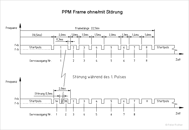
The stream would need to look something like this (although the frame length may differ from transmitter to transmitter)


(refer to the top image only)[/li]
[li]Would [/li]
[li]Have you got some example code that looks like this?

This now leads me to another question:
Some of my switches are 3 position (on-on-on), with each position representing a required width of a single channel.
ie. If a 3 pos switch is representing say channel 6, position 1 would equal 1000μs, position 2 would equal 1500μs, and position 3 would equal 2000μs. [/li]
[li]Would I need to configure my switch as a potentiometer to output a given resistance at the 3 positions, so it would then be connected to a single input on the maestro.[/li]
[li]Or do I connect the switch to the Maestro with each position going to an individual input.
[list=a]
[*]As it’s just an on/off, would this need to be connected to digital inputs, or can it still be connected to an analog input?[/li][/ol]

I will share my project once it’s finished, for now my research continues to make sure I get the correct Maestros. If I need digital inputs for the switches, then I will need a Maestro24. Also the inputs required ay change depending on how I can connect my switches, and outputs will change depending on if I can get the RC CPPM stream to work. Last question:[/:m]
[li]Are the digital inputs on the Maestro24 also configurable as servo outputs?
[ol][
]Are they more precise than the analog pins?[/li]
[li]Would they be more suited to the RC CPPM stream I am trying to code?[/li][/ol][/*:m][/list:o]

edit: changed ms to μs

I have just realised that the Maestros pulse width rage is from 64μs to 4080μs. If I understand this correctly, I will not get a short enough pulse to “build” the CPPM stream.
Or am I getting confused? My brain is hurting now.

edit: corrected ms to μs

Actually,

A CPPM stream needs 1ms (milliseconds)
The maestro can go as low as 67μs (0.067milliseconds), with a resolution of 0.25μs (0.00025milliseconds)

So I think I should be able to code a PPM stream out of the maestro.
This is good news I think.

If I understand this correctly here, for a CPPM stream I need a pulse of width 300μs to define the channel. The time between channels is the value of the channel.
Then I need a larger gap (of 10.5ms) to signal the start of the next stream.

This shouldn’t be too hard to code.

So I have built some code for my purpose, just starting by having 8 servo outputs.
Im using 3 Maestro12s
Maestro 1 as the main board, outputting the signals.
Maestro 2 is the pots inputs.
Maestro 3 is the switch inputs.

Maestro 1 will be connected to the PC by USB. The others will be daisy-chained by serial ports.

Questions:
[ol][li]In the sub routines “sub maestro_2” and “sub maestro_3”, Im assuming I change the 0xFF lines to suit the actual addresses of the Maestros?[/li]
[li]Are my calculations correct in the calculations notes section of the code?[/li]
[li]What format can I save this file in?[/li]
[li]Is the code correct? (I don’t have my Maestros yet, so I can’t test)[/li]
[li]Are there any ways I can improve this code?
[list=a][]Would it be better to have the code for the pots on the pot Maestro (2) and the switch code on the switch Maestro, and have them “push” the signal to Maestro 1, rather than have Maestro 1 do all the work by “pulling” the signal from the other maestros?[/li][/ol][/:m][/list:o]

[code]#This file uses analog inputs to generate servo PWM signal on 8 servo channels

#Calculation Notes:
#Pots range from 0-1023
#Scale up to get full range 4000-8092 = 1-2ms
#If an exact pulse width is required, calculate as follows, to get the required servo value:
#P=Pulse width (ms)

P/(2/8092)

=P/.0002472

#Maestro 1 (Outputs)
#Pin 0=Free
#Pin 1=CH1 Throttle
#Pin 1=CH2 Aileron
#Pin 3=CH3 Elevator
#Pin 4=CH4 Rudder
#Pin 5=CH5
#Pin 6=CH6
#Pin 7=CH7
#Pin 8=CH8
#Pin 9=Free
#Pin 10=Free
#Pin 11=Free

#Maestro 2 (Pots)
#Pin 0=Free
#Pin 1=Throttle
#Pin 1=Aileron
#Pin 3=Elevator
#Pin 4=Rudder
#Pin 5=Left Slider (S-3)
#Pin 6=Right Slider (S-4)
#Pin 7=Gimbal Joystick Pitch
#Pin 8=Gimbal Joystick Pan
#Pin 9=Free
#Pin 10=Free
#Pin 11=Free

#Maestro 3 (Switches)
#Pin 0=Free
#Pin 1=Switch 1 (S-A)
#Pin 2=Switch 2 (S-B)
#Pin 3=Switch 3 (S-C)
#Pin 4=Switch 4 (S-D)
#Pin 5=Switch 5 (S-E)
#Pin 6=Switch 6 (S-F)
#Pin 7=Switch 7 (S-G)
#Pin 8=Switch 8 (S-H)
#Pin 9=Switch 9 (S-1)
#Pin 10=Switch 10 (S-2)
#Pin 11=Free

#Defines serial port of Maestro 2
sub maestro_2
0xFF serial_send_byte serial_send_byte serial_send_byte
return

#Defines serial port of Maestro 2
sub maestro_3
0xFF serial_send_byte serial_send_byte serial_send_byte
return

Sets CH1 Throttle PWM.

begin
1 maestro_2 get_position
4 times 4000 plus
1 servo
repeat

Sets CH2 Aileron PWM.

begin
2 maestro_2 get_position
4 times 4000 plus
2 servo
repeat

Sets CH3 Elevator PWM.

begin
3 maestro_2 get_position
4 times 4000 plus
3 servo
repeat

Sets CH4 Rudder PWM.

begin
4 maestro_2 get_position
4 times 4000 plus
4 servo
repeat

Sets CH5 ? PWM from a Pot.

#begin

? maestro_X get_position #replace “?” and “X”

4 times 4000 plus

5 servo

#repeat

Sets CH5 ? PWM from a Switch.

#begin
#See examples below
#repeat

Sets CH6 ? PWM from a Pot.

#begin

? maestro_X get_position #replace “?” and “X”

4 times 4000 plus

6 servo

#repeat

Sets CH6 ? PWM from a Switch.

#begin
#See examples below
#repeat

Sets CH7 ? PWM from a Pot.

#begin

? maestro_X get_position #replace “?” and “X”

4 times 4000 plus

7 servo

#repeat

Sets CH7 ? PWM from Switch.

#begin
#See examples below
#repeat

Sets CH8 ? PWM from a Pot.

#begin

? maestro_X get_position #replace “?” and “X”

4 times 4000 plus

8 servo

#repeat

Sets CH8 ? PWM from a Switch.

#begin
#See examples below
#repeat

#Example switches

##2 position toggle switch pot.
begin
? maestro_3 get_position #replace “?” with input pin number from maestro_3
dup 513 less_than
if
4200 #1050μs for values 0-512
else
7800 #1950μs for values 512-1023
endif
? servo #replace “?” with output pin number on maestro_1
drop
repeat

##3 position toggle switch pot.
begin
? maestro_3 get_position #replace “?” with input pin number from maestro_3
dup 342 less_than
if
4200 #(1050μs) for values 0-341
else
dup 682 less_than
if
6000 #(1500μs) for values 341-681
else
7800 #(1950μs) for values 681-1023
endif
endif
? servo #replace “?” with output pin number on maestro_1
drop
repeat

##6 position rotary switch pot.
begin
? maestro_3 get_position #replace “?” with input pin number from maestro_3
dup 171 less_than
if
4248 #(1050μs) for values 0-170
else
dup 342 less_than
if
4977 #(1230μs) for values 170-341
else
dup 513 less_than
if
5705 #(1410μs) for values 341-512
else
dup 683 less_than
if
6433 #(1590μs) for values 512-682
else
dup 854 less_than
if
7161 #(1770μs) for values 682-853
else
7890 #(1950μs) for values 853-1023
endif
endif
endif
endif
endif
? servo #replace “?” with output pin number on maestro_1
drop
repeat
[/code]

I do not think it would be very practical to try to use the Maestro to output PPM signals since the Maestro does not provide the tools necessary to have precise control over the sequence of pulses sent.

To answer your questions about your 3 position switch, you can configure it so that it gives a different voltage (between 0V and 5V) at each position and read it using an analog input channel (i.e. a Maestro channel between 0-11 configured as an input) and do some processing or use separate channels for each position. Please note that even though channels 0 through 11 are analog inputs, you can use them to read digital signals (such as switches) too. As for the digital pins on the 24-channel Maestro (pins 12-23), they can all be individually configured as servo outputs, digital inputs, or digital outputs. More information on this can be found in the “Channel Settings” section of the Maestro user’s guide, under the “Mode” heading. They should not have any noticeable difference in precision over the analog pins.

I only briefly looked over your script, but I noticed that there are several BEGIN/REPEAT blocks that will never be reached because the infinite loop before them never terminates. If you ran your current script, your first BEGIN/REPEAT block would be the only part of the code reached. Also, in your maestro_2 and maestro_3 subroutines, I am not sure what serial commands you are trying to send. It looks like you are trying to send 0xFF along with another integer, but you call serial_send_byte three times with only those two arguments on the stack. I recommend waiting until you have a Maestro to test some scripts on so you can become a little more familiar with it first. If you still have questions about scripting then, and can post simplified code that demonstrates the problem, I would be happy to look over your revised script.

-Brandon

Thanks again Brandon.

I’ve ordered my Maestros and will test my script out. If I have issues, I’ll get back to you.