
I’m always on the lookout for suitable gearmotors, scrounged from discarded equipment if possible. Key features are voltage, current draw and rpm, but the latter is not so simple to measure. I made an adapter that plugs into a port on the Orangutan, counts revolutions on a homemade codewheel attached to the motor shaft and displays the rpm (or milliseconds/revolution) on the LCD display.
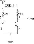
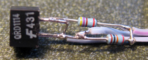
The detector is a QRD1114 phototransistor/IR LED pair(about US$1.25 at many sources) connected to PC5. The schematic is shown below, together with a picture. I put the assembly into a pen body for support.
For this project I used the original Orangutan with the ATmega8 chip. Sadly, the only available external interrupt lines are dedicated to the LCD so I was forced to count revolutions within the main loop.
The code uses a timer0 interrupt to generate 4000 ticks/second, which is used to time the codewheel cycle. This implementation has been tested to 1500 rpms and does not seem to miss counts. It cannot go over about 3200 rpm because of the integer math.
Note: because of the unknown amount of time required to print the results within the main loop, the measured rpms are probably a bit high. The test at 1500 rpm was independently checked out using a precision encoder, so I doubt if the error is greater than one percent even at this speed. The next version, using interrupts on the mega168 should solve this problem, but other suggestions are welcome!
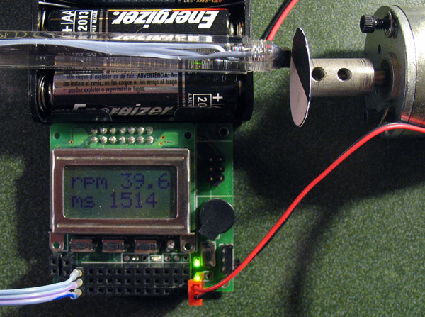
The photo above shows a Pittman gearmotor salvaged from a 1978 vintage 36 inch pen plotter. The motor is rated at 6V/1 amp and is internally geared 18:1. It is running off of a 1.4 volt 1 amp source and is chugging along nicely at, well, 39.6 rpm! (At higher rpms, the fraction, and then the decimal point disappear under the aluminum frame at the right of the display).
Code is below. Incidentally, I finally figured out how to use printf() with the LCD, but the printf routines consume about 2K bytes of program code.
Cheers, Jim
Code:(download from
uoxray.uoregon.edu/orangutan/rpm.c and lcd.c for tabbed versions.)
/*
rpm measurements using the Orangutan
Atmega8 version, last update 6/4/2007
FOSC=8MHz
sjames_remington at yahoo dot com

*/
#include <avr/interrupt.h>
#include <avr/io.h>
#include <stdio.h>
#include <stdlib.h>

#define F_CPU 8000000UL

/*
 *  Function prototypes
 *	Use home-rolled delays in main
 */

void	Delay_us ( unsigned int microseconds );
void	Delay_ms ( unsigned int milliseconds );
void LCDInit(void);
void LCDSendData(unsigned char data);
void LCDSendCommand(unsigned char command);
void LCDPrintString(const unsigned char *string);
void LCDGotoXY(unsigned char x,unsigned char y);
extern int lcd_putchar(char c, FILE *stream);

// globals

volatile unsigned long ticks;
volatile int secs;

FILE lcd_str = FDEV_SETUP_STREAM(lcd_putchar, NULL, _FDEV_SETUP_WRITE);

#include "lcd.c"

int lcd_putchar(char c, FILE *stream) {
/*
 * Send character c to the LCD for use with printf
 */
	LCDSendData(c);
	return 0;
}

/*
 * Timer0 overflow interrupt handler. Counts system clock/8/250 -- provides global ticks at 4 kHz
 */

ISR(TIMER0_OVF_vect)
{
	static unsigned int pcount = 4000;	//4000 ticks per second

	TCNT0 = 6; 	ticks++; 	//reload counter; 250 to overflow
	if (pcount-- == 0) {  	//decrement tick counter and update runtime seconds
		secs++; pcount=4000;
		}
}

void timer_init(void) {

// set up Timer0 to provide 0.25 ms ticks

	TCCR0  = (1<<CS01);  //clock/8
	TIMSK |= (1<<TOIE0); // enable int on overflow
	TCNT0=6;	//250 counts to overflow
}

int main( void )
{
	long int now,then;
	int t,period,rpm;

	timer_init();
	LCDInit();
	stdout = &lcd_str;			// associate stream with stdout

	ticks=0;

	printf("RPM 0.1");
	Delay_ms(2000);				//allow user to admire the splash screen
	sei();						//enable timer interrupts

	//first pass synchronizes edges

	while( (PINC&(1<<PC5)) ==0);	//seeing white, wait till black
	while( (PINC&(1<<PC5)) !=0);	//seeing black, wait till white

	while(1){
	then=ticks;						//now time one full revolution
	while( (PINC&(1<<PC5)) ==0);	//seeing white, wait till black
	while( (PINC&(1<<PC5)) !=0);	//seeing black, wait till white
	now=ticks;
	period=now-then;

	rpm=2400000L/(long) period;		//convert to rpm*10 (1 rev/second = 4000 ticks)
	t=rpm%10; 						//one decimal point (avoid loading floating point routines)
	rpm=rpm/10;						//integer value

	LCDSendCommand(LCD_Clear);
	printf("rpm %d.%d",rpm,t);		//print rpm string
	LCDSendCommand(LCD_Line2);
	printf("ms %d",period>>2);		//print period in milliseconds

	} //end while(1)

//end of main
}

/*
 *  Delay_us
 *
 *  wait in a loop for the specified number of microseconds.
 *
 */

void Delay_us( unsigned int microseconds )
{
    register unsigned int loop_count;
    /* 8mhz clock, 4 instructions per loop_count  */
    loop_count = microseconds<<1;

    __asm__ volatile (
        "1: sbiw %0,1" "\n\t"
        "brne 1b"
        : "=w" ( loop_count )
        : "0"  ( loop_count )
    );
}

/* Delay_ms
 *
 *  wait in a loop for the specified number of milliseconds.
 *
 */

void Delay_ms( unsigned int milliseconds )
{
    uint16_t i;

    for ( i = 0; i < milliseconds; ++i )
    {
        Delay_us( 1000 );
    }
}