I bought a Simple Motor Controller 18v7 to power a 12 Volt, 24 Watt windshield wiper motor. I’m using a 12 Volt, 5 Amp wall wart as a power supply. The controller worked fine for quite a while. I monitored it using the Pololu Simple Motor Control Center.
Then the controller started to get a lot of serial errors when I was sending it data through an Arduino microcontroller. Then it started to heat up whenever Vin was applied, even if the motor speed was set at zero. Now everything seems fine, but it no longer powers the motor.
The yellow LED on the controller pulses as though it is sending power to the motor, but the motor does not turn. My voltmeter shows the motor is getting about 0.2 Volts, when it supposed to be getting full power.
I’m sorry you are having problems with the Simple Motor Controller 18v7.
It sounds like the problems started when you tried to send commands to it through your Arduino. What connections did you make between the Arduino and the Simple Motor Controller? Which model of Arduino are you using and does it run at 5 V or some other voltage?
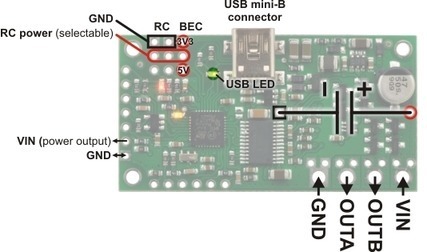
Did you connect the motor and power supply to the large GND, VIN, OUTA, and OUTB holes indicated in this diagram? Did you solder in the big blue through-hole capacitor included with the controller or buy the assembled version where the capacitor is already soldered in?
Did you make any changes to the wiring later after the controller started overheating?
When the motor controller is in the state where you think it should be driving the motor but isn’t, what does the “Current Speed” in the Status tab of the Simple Motor Control Center say? Are there any errors reported in the Errors box?
I connected some of my Arduino Deucemilanove digital output pins to the Simple Motor Controller serial input pins and sent speed signals using the Arduino’s serial communication library. The Arduino runs at 5 Volts.
I also had my computer hooked up to the Simple Motor Controller by USB, and monitored the controller using the Simple Motor Controller Center.
Everything worked fine for quite a while, as I experimented off and on for a couple of weeks. Then I started getting a lot of serial errors showing up in the Simple Motor Control Center.
Yes.
I soldered the through-hole capacitor in myself.
No. But before it started overheating, I wired a ceramic capacitor across the motor terminals to try to cut down on electrical noise and stop the serial errors.
It shows the Current Speed as going from 0 to 100%. In other words, it shows the motor as moving at the target speed when in fact the motor is not moving.
No.
Just an update. I hooked the motor and controller up just now. It performed as before for a while. That is, the Simple Motor Control Center would say the motor was moving, but it was not.
Then I moved the speed slider to -100%. Something made a whine (I think it was the motor controller rather than the motor). I noticed a burning smell. The temperature reading started rising quickly to about 40 degrees. But the motor did not move.
I quickly moved the speed slider to zero. The temperature went back down. Everything seemed the same. But now whenever I try to move the speed slider away from zero, I get a “Motor driver error” and the motor shows as stopped.
I took away all power from everything. The Simple Motor Controller still smells a little burned.
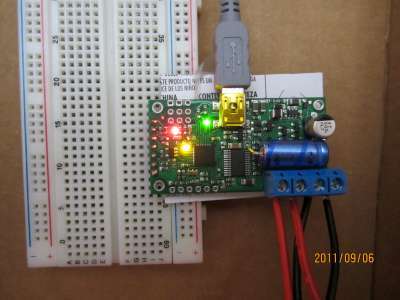
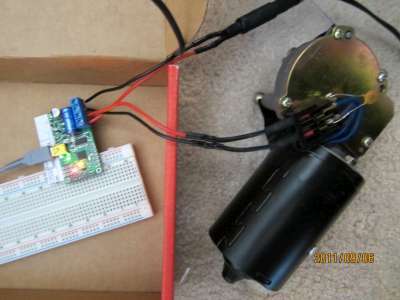
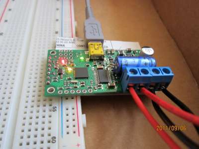
Smelling something burning is a pretty bad sign, and I suspect your SMC is now permanently damaged. If you want to try again with another Simple Motor Controller, we can probably at least get you some sort of discount on a replacement, but first we should try to get to the bottom of what caused the problems with your current unit. It sounds to me like you might have a short somewhere in your system. Can you post some pictures that clearly show how everything is connected? Did anything change shortly before you started getting all those serial errors?
Like you I suspected a short. But I don’t see anything like that on the connectors to the board.
The serial errors started happening while I was doing experimenting. I was changing software, but I changed nothing on the hardware side. The only thing I did change later was to add the ceramic capacitor, but I can’t see how that would cause the problem.
I’m not sure if the serial errors are connected to the burning issue, or if they are two separate issues.
A discount would be nice. I would like to get a replacement Simple Motor Controller to continue with my testing and experimenting. I’m trying to set the windshield wiper motor up as a servo motor, so that I can send the Arduino an angle and the motor will turn to that angle.
Do you think the Simple Motor Controller will work for that? The specifications seem to show that it should. As you say, though, it would be nice if we could figure out what the problem was before starting over with a new one.
I apologize for my delayed reply. Thank you for the pictures. In general, I am concerned that your power supply, and possibly the SMC version you are using, are underpowered for your motor. Do you know the stall current of your motor at 12 V?
You can certainly use the SMC as the motor controller portion of a servo, but you would have to close the feedback loop yourself (e.g. with your Arduino). We also offer motor controllers with built-in support for feedback that close the loop for you. Please see our jrk motor controllers with feedback for more information.
Thanks for your reply. No problem about the delay.
The motor is rated at 24 Watts, so the continuous current would be 2 Amps at 12 Volts. I’m not sure what the stall current of the motor is. I never did load up the motor, nor do I recall ever reversing it quickly. I’ve just been using the motor to test and develop my software for the Arduino.
Even if the motor did draw stall current, it doesn’t seem like an underpowered power supply would burn out the motor controller, does it? I would not think the stall current would get above 30 Amps, which is the maximum for the 12v7.
What do you think?
My plan was to use the motor and controller to develop the software for a servo-type motor. That is, I give the Arduino an angle in degrees in digital form, and the motor turns to that angle. I’m just using a potentiometer now, but want to find a better Hall absolute position sensor. I may need a more powerful motor, too.
The Pololu jrk motor controllers with feedback are very nicely done, and your software package looks great. I looked into the 12v12 model, since that seemed powerful enough. But it did not seem that there was quite enough flexibility in your software to customize it to do what I want to do.
UPDATE: The stall current of the motor is, according to one person’s test, close to 14 Amps.
My main concern is your power supply, which is not appropriate for such a motor and could be handling the demands of your motor very poorly. Whenever your motor accelerates rapidly, it could be trying to draw nearly the full stall current, and I’m not sure how your power supply will respond to such spikes. I suspect the voltage could be spiking wildly in response, potentially to levels above what the motor driver is rated for (i.e. over 30 V). In general, wall warts are not good supplies for motors, especially powerful ones like you are using. I would strongly recommend using batteries, but if you need to use a wall wart, you should take additional steps to limit voltage spikes on the controller input (I also recommend looking at the input voltage with a scope if you have one).
I also had a thought about your serial errors. Can you tell me exactly what connections you had between your SMC and the Arduino? If you did not have a good common ground between the two, that could have been responsible for your communication issues.
What customization options do you need that the jrk is lacking? Note that we have a version of the jrk firmware that will work with absolution-position Hall-effect sensors that output analog voltages, such as this
I’ve just been using the wall wart for convenience. As I said, I have not put any load on the motor, and have not really accelerated it either. I’ve just been using it to turn a potentiometer for testing and developing my software.
For my application, I will be using a 12-Volt deep discharge battery to power the motor (and several other things), and probably a different motor and controller as well. The wall wart, this motor, and the Simple Motor Controller just seemed a convenient way to do this development.
I did not think the wall wart would burn out the Simple Motor Controller. Is that what you think happened? Would a bench power supply I built out of an old PC power supply be safer? That power supply can put out 34 Amps at 12 Volts.
As to the serial communication, I had hooked up the the Ground, Vin, Rx and Tx pins on the Simple Motor Controller to the appropriate pins on the Arduino. That worked well for quite a while, so I doubt that the problem was a bad ground connection. But it’s hard to say.
Finally, the customization problem with the jrk was more in dealing with the input. I’m designing a modular system that needs to take an angle input in digital form, and turn to the motor to that angle. I could not see how I could massage the input using the jrk. Since I would need a front end anyway, I thought I would use the Arduino and write my own code.
But I’ll take another look at the jrk. It is a nicely thought-out design, and I like the software you have put together. Maybe the jrk can be used here.
UPDATE: Thanks for the note about the absolute position sensor that works with the jrk controllers. That sensor is a good one for my application. Pricey, but good. And I had not seen it before.
After a busy month, I’m back to this project. If I use my bench power supply, do you think I can safely use the 18v7 Simple Motor Controller without burning it out again?
Your bench power supply is probably not adequate for a motor like that, either. How much current can it deliver? I also recommend upgrading to a more powerful SMC, such as the 18v15. That way there’s less chance of having problems once your motor is under load, and your controller will generally run cooler.
Note that if you are limited by your power supply, you should take extra steps to avoid current spikes that might exceed what your power supply can deliver (e.g. enable the SMC’s acceleration-limiting feature).
The bench power supply is made from an old 550 watt computer power supply. It is rated to put out 34 Amps at 12 Volts. Should be plenty.
As I mentioned, I have been treating the motor gently. No fast starts or stops or reverses. I’m just trying to get the motor to act like a servo, so it never even turns much. That’s why I cannot figure out why the Simple Motor Controller burned out.
But I probably will try the 18v15 Simple Motor Controller. I’d try the jrk, but I would hate to burn it out too.
The VNH2SP30 motor driver used by the jrk 12v12 is quite robust and features a lot of built-in protection, so I think you can safely use it in your application, especially if you use a more capable power supply like your 550 W bench supply. No matter which controller you use, if you have access to an oscilloscope, you should use it to monitor your power supply to make sure that there isn’t a lot of noise on the line while the motor is running and to keep an eye out for LC voltage spikes when you apply power. If there is a lot of noise or your power lines are long, you might want to add more power capacitors.
I believe that you think you were using the motor gently, and perhaps you were. However, if you were using PID to get the motor to act as a servo, I think you could have been putting more stress on it than it might have outwardly appeared. Even when you were at your target position, the motor could have been rapidly accelerating back and forth if your PID constants were not well tuned.
Yes, we wrote custom firmware to let the motor take the shortest path to its target position when using special encoders like this and tested it with that particular encoder. Specifically, the custom firmware assumes there is positional wrap-around (i.e. the maximum position connects to the minimum position) while the default jrk firmware does not. If you want to use that encoder (or anything like it that can rotate continuously) and want your final system to be able to take advantage of positional wrap-around, you should contact us directly to get this custom firmware.
For my application, I want to control my motor like a servo. I just need an electrical angle of at most 180 degrees. Probably 90 degrees would be fine. Maybe even 60 degrees. But it would be nice to get better than the 0.5 to 0.9 degree resolution that the encoder you used gets.
I’ll keep looking for something. For now, I’ll just use a potentiometer. It will be good to get the jrk controller and see how it works in my application.
Just an update. The 12v12 jrk controller came already, and it looks like it will work very well for my application. Both the board and the software are well thought out, and make it easy to do just what I want to do. Now I just need to get a better rotary position sensor to replace my potentiometer.
It did take me about two hours to get the jrk controller to work. The first problem was realizing that I had to click on the box “Apply changes” after making any change. Realizing that let me get the motor moving.
Then I could not get the PID algorithm to work. After about an hour, I noticed that the P, I and D terms were all set to zero. For some reason I thought at least the P term would be set to one. Once I noticed that, everything worked fine.
Also, I should note that the motor has never pulled more than 5 Amps. I set the max current to that level, and did starts and stops, and it never tripped the “exceeded max current” error. But I am using my power supply instead of the wall wart, to be more confident that the voltage will be regulated.
Thanks for your help, Ben.
UPDATE: I spoke too soon. The motor sometimes pulls up to 15 Amps if I work it hard. So it’s very possible that, as you suspected, using the wall wart with the 18v7 Simple Motor Controller that I had caused the burn-out of the controller.