
Overview
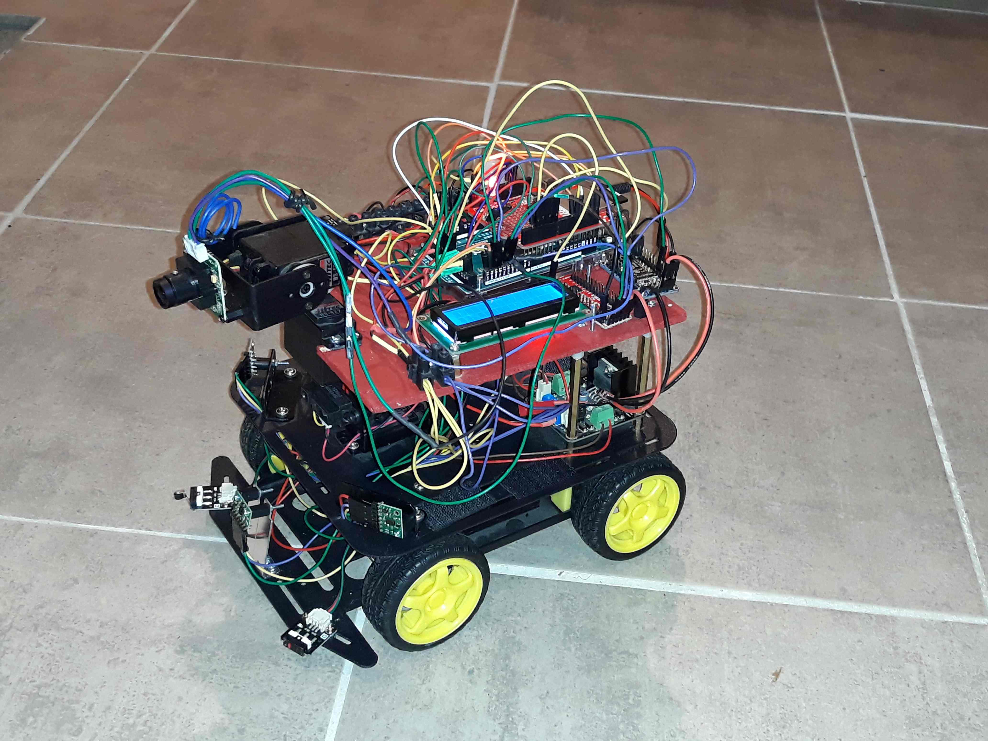
My Robot is controlled by the Arduino MEGA2560.
Quite all the features of the MEGA2560 are used: 3 Serial interfaces, I2C, SPI, PWM, ADC and 2 interrupts. This is why I have chosen the MEGA2560 which offers such large number of interfaces. But note that MEGA2560 is a little bit limited regarding the interrupts because 4 of the 6 interrupts are not available if I2C and Serial2 are used.
The only features missing in the MEGA2560 are Bluetooth and WIFI connections. For this purpose I have added one nRF52832 to handle Bluetooth and one ESP8266 for WIFI processing. The first one manages the commands received from the user interface running on Android, the second one send data and pictures to a Raspberry PI.
Initially I have used also an ESP8266 to manage command received from a my PC on Windows but the WIFI was too much power consuming so I have migrated this part to Android and BLE Bluetooth, so now the commands are sent from my mobile.
Here the global flow:

What is the purpose of this Robot? Nothing J except to discover few devices around the Arduino eco system and build a communication protocol between windows, ESP, Arduino and PI.
Seriously this robot is able to process several commands, to run independently, to detect environmental changes and then send alerts and pictures to the Raspberry PI.
For its part, the PI stores the data into text files and MySQL Database, and sends them via email.
Devices
Now let’s discuss more in detail about the devices implemented. Below the list of devices and the implementation diagram.
Devices
nRF52832
ESP8266
4 motors
2 H-bridges
2 Contact sensors
Sharp IR
Servo for IR
3 ToF
Compass
LCD
RGB led
Buzzer
Camera
Tilt&Pan servos for Camera
SD Card
RTC
Brightness sensor
Temperature & Humidity sensor
Motion sensor
Sound sensor
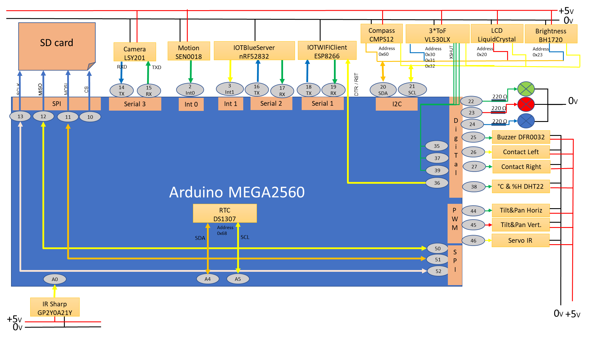
First of all, there are 4 motors controlled by 2 H-bridges managed using PWM and digital pins. They have a dedicated alimentation Lipo in order to not disturb the MEGA2560 but don’t forget to connect the ground otherwise PWM will not work.
In order to allow the robot to run independently, the following devices are implemented:
3 Time Of Flight TOF connected to I2C indicates with a good precision the distance (max 1,20 m) between the robot and a potential obstacle. One TOF is set on the front of the robot, the 2 others are set on the left and right sides with an angle of 45° from the front. Their pin Shutdown is managed in order to set different I2C address for each device. They are configured to allow measure every 33ms if required. Only the median from a sample of measures is taken in account in order to avoid erratic measures.
One IR Sharp connected to ADC and mount on a servo checks the distance (max 0.80m) with an obstacle around the robot (left and right). Note that it is less precise than the TOF. The servo is controlled by PWM and allow to move the IR Sharp from -180° to + 180°, more than the TOF that are statics.
2 contact sensors are implemented on left and right side to detect hit, in case the robot didn’t detect the obstacle on time!
Each 165ms(33*5: nb sample measures), the Front TOF measure the distance between the robot and a potential obstacle.
If the distance is smaller than the Distance minimum, then, the robot turns 45° to the direction where this is no obstacle or it turns back if it detects obstacle on left and right sides. The IR Sharp is used to check obstacle around as it is mounted on a Tilt&Pan. A compass connected to I2C provides the direction in order to control the turn. The robot follows also this procedure in case of hint detected by the contact sensors.
If the distance is between Distance minimum and the Distance nominal, then the robot checks the distances measured by the left and right TOF and push off to the best direction by accelerate/decelerate the motor on a side.
If the distance is greater than the Distance nominal, then the robot continue to run straight forward.
The robot can also check the environment and send alerts in case of abnormal changes. The parameters monitored are the following:
Motion is detected by a sensor that triggers an interrupt on the MEGA2560. So this alert is in real-time.
Temperature & Humidity connected to Digital pin allows the detection of abnormal variation of temperature or humidity
Brightness is also monitored by a sensor connected to I2C
I have tried several sound sensors buy none of them is adequate: they don’t detect when I increase the volume of my speakers. Don’t hesitate to recommend one!
In case of alert, the robot takes pictures using a camera mount on a tilt pan. So the camera can move from -180° to + 180° horizontally and vertically. The camera is connected to Serial3 and the 2 servos of the Tilt pan are controlled by PWM.
The pictures are stored into jpeg files on a SD Card connected with SPI. Then the MEGA2560 send them via Serial1 at 38400 bauds to the ESP8266 Client and then to the Raspberry PI by WIFI with the data captured by the robot
There are PHP programs on the Raspberry PI that stores in TXT files and in a MySQL database the data received. In case of alerts, the Raspberry PI sends email with these data and the corresponding pictures attached.
In addition of all these devices, there are some other components to monitor the system: RGB led and buzzer connected to digital pins, Real Time Clock RTC and LCD connected to I2C.
There are mainly used to understand in real-time what is the doing the system as there is no more connection and logging to the IDE standard Serial port when the robot runs. The log is written into a file on the SD-Card, with trace and RTC timestamps, so it can be analyzed later.
Below the core part with the MEGA2650, nRF52832 and ESP8266 + some devices (LCD, Camera,Tilt&Pan, compass, motion sensor, Sd Card, RTC, brightness sensor)

Commands
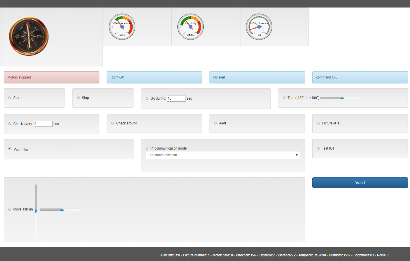
This robot can run independently but he can also be managed by a User Interface UI running either on Android either on Windows.
On Windows, the UI is written in HTML/jQuery using google widgets. As explained previously, the commands are sent via WIFI to a dedicated ESP8266 Server that interrupts the MEGA2650 prior to send it via Serial2 the command. So the MEGA2650 is not blocking to wait for a command, but he can manage it as soon as needed.
The responses are transmitted back to the ESP8266 and then to the UI. Note that the biggest inconvenient with ESP8266 is the consumption, about 80mah. So the LIPO 780maH is empty after a couple of hours, so I need to switch off manually the ESP8266 Server as soon as I don’t need any more of the UI.
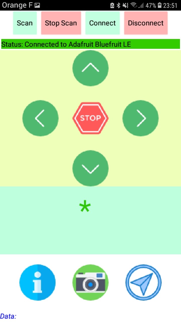
This is the reason why I have built an other interface based on Android and Bluetooth.
This UI is written using MIT App Inventor that allows creating software applications for Android easily. The commands are sent via BLE Bluetooth using a Serial service to the nRF52832 that interrupts the MEGA2650 prior to send it via Serial2 the command. So the MEGA2650 is not blocking to wait for a command, but he can manage it as soon as needed.
Note that the Bluetooth buffer is very small (20 bytes) compare to WIFI.
The commands are the following:
| Command | Purpose |
|---|---|
| Test IOT | Test communication with the ESP8266 server and the robot |
| Check every n sec | Check every n seconds |
| Stop | Stop |
| Picture | Make picture and return the picture number |
| Move Tilt&Pan | Move Tilt&Pan Horizontally and Vertically |
| Check around | Check if there is an obstacle and return the result |
| Get data | Get data and return them |
| PI Communication mode | Define the communication mode between the Robot and the Raspberry PI: |
- None
- Alert only
- Alert and Data every n seconds|
Below the User Interface for Windows in HTML/JS&JQuery build with bootstrap and Google charts.
Below the User Interface for Android built with MIT App Inventor.
Communication to Raspberry PI
The ESP8266 Client is in charge sending Data and Picture to the Raspberry PI using WIFI.
In order to reduce consumption, it is always in deep sleep mode and it is wake up by a low pulse of 10ms to its pin DTR/RTS triggered by the Arduino prior sending any data or picture via the serial interface. Note that as the ESP boot procedure uses also Serial to log some information, the startup of the ESP was sometimes blocked to I swap the Serial pin of the ESP just after the start to avoid conflict with Arduino.
As soon as the data are sent, the Arduino send a sleep command the ESP to go back in deep sleep mode.
Software
In term of software, I have written in C++ one lib per device and there is a main program Robot that handle the core processing of the MEGA2560 and that calls the functions in the libs.
At the end the program is quiet large, hopefully the MEGA 2560 has enough memory to run it, but for sure you can’t run it on Uno. Note that all the string for logging are stored in Flash memory to win space on data memory.
In addition there are 2 main programs for the ESP Server ( Bluetooth or WIFI based ) and the ESP Client .
There ara also some tools:
Set the time of the RTC
Store WIFI credentials in the flash memory of the ESP (so they are not displayed in Git!)
Calibrate the Compass
Most of the code source has been found in the net (thanks to open source!) and then customized/improved. One key point is that most of the time the sources found on the net don’t handle properly the errors so I have completed this part, mainly on the I2C part.
Each device been tested alone with dedicated sketch before to be integrated to the core program. This is very useful to better understand the behavior and to know the limitation. For example, sometimes devices provide erratic measurements so it is more secure to get a sample of measures and compute the median.
The initialization part is also very critical and I have added for each device some tests cases during this phase in order to validate before starting that everything is ready. For example change the I2C address of the TOF in order to avoid bus conflicts.
I have also build a lib to define a protocol between nRF, ESP and Arduino to ensure a good quality of transmission on the Serial interface and to avoid deadlock. This is mandatory as the Serial interface is not secure, some bytes can be lost it the Serial buffer is full and the reader not ready. The logic of the protocol is described below:
In term of logging, 3 modes are available:
- No logging
- Logging on Serial
- Logging on file stored on the SD Card
The last mode is useful for autonomous run. Several macros are defined to facilitate the logging, including trace and timestamps. All the strings are stored in Flash memory to save space in the data memory.
Source code
Source code is located in 4 Git repos, the first one contains everything for Arduino, nRF and ESP:
The second one contains the source code of the Android User Interface:
The third one contains the source code of the Windows User Interface:
The fourth one contains the source code for the Raspberry PI:
What’s new
- Adding 2 TOF on left and buy side
- 3 Logging mode are available (No logging, Serial, SD Card)
- Send command via Bluetooth BLE from Android mobile instead of WIFI from Windows PC