
Ben
just one quick question
do you mean to write this with braces?
while (!(PINC & (1 << PC3))); // wait while pin PC3 is low
{
error = 0;
TCNT1 = 0; // effectively start timing now
}
please let me know
Ben
just one quick question
do you mean to write this with braces?
while (!(PINC & (1 << PC3))); // wait while pin PC3 is low
{
error = 0;
TCNT1 = 0; // effectively start timing now
}
please let me know
Ben
There is an important factor I recently discovered. in RC pulses there is a 20ms delay between each pulse, unless
this is accounted for, an incorrect reading may occur.
found here:
superdroidrobots.com/product_info/RC.htm
Here is a revision and results:
based on the code below in actually tests
The motor Function gets exec over and over without stopping regardless of pulse or position or the r/c channel position.
The LED function never runs?
Problems I have already thought of:
I did not load the proper hex file or this new hex version did not overwrite and replace previous versions in FLASH ram?
But according to the diagnostics everything is loading fine. To make sure I have the proper Hex file, I deleted the Hex,
recompiled, then “PROGRAM” the baby-0168 again.
AVR step thru
When I simulate running using a step thru I set the bit low then step then I set it high then step in all cases the steps
get passed the 2nd while loop and fall down to the “if (!error)” and enter the if statement then the step bypasses all other
code and jumps back up to “while(1)”
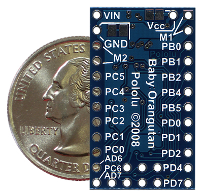
I would like to double check and make sure I am using the right pin shown here is PC3 the pin I am feeding an r/c signal to
pololu.com/picture/thumbnail … g?size=600
void TurnOnLED()
{
	DDRD |= 1 << PD1;		// set LED pin PD1 to output

	PORTD |= 1 << PD1; 		// LED on
	delay_ms( 900 );			// delay 900 ms
	PORTD &= ~( 1 << PD1 );	// LED off
	delay_ms( 900 );			// delay 900 ms
	PORTD |= 1 << PD1; 		// LED on
	delay_ms( 100 );			// delay 100 ms
	PORTD &= ~( 1 << PD1 );	// LED off
}

void Move2Motors()
  {
          	 M1_FORWARD(100);  // open door
			 delay_ms(1500);
			 M1_FORWARD(0);

             M2_FORWARD(75);  // control shaft
			 delay_ms(1000);
			 M2_FORWARD(0);

			 M1_REVERSE(100); // close door
			 delay_ms(1500);
			 M1_REVERSE(0);

			 M2_REVERSE(75);  // return control shaft
			 delay_ms(1000);
			 M2_REVERSE(0);
  }


int main()
{
int PROC_CTL = 1;
unsigned char error = 0;  			// ignore this pulse if error is 1
unsigned char pulseWidth;

TCCR1B = 0x02;     					// clock timer1 using I/O clock divided by 8 (2.5 MHz)

while (1)
{

  while (!(PINC & (1 << PC3))); 	// wait while pin PC3 is low

  delay_ms(20);						// wait 20ms in between pulses standard rc spec
  error = 0;
  TCNT1 = 0;  						// effectively start timing now

  while (PINC & (1 << PC3)) 		// wait while pin PC3 is high
  	{
    if (TCNT1 > 5000)
      error = 1;  					// identify this as a bad pulse before timer1 overflows
  	}


  if (!error)						 // no error detected
  	{
	pulseWidth = TCNT1 * 0.4;		 // convert to micro Seconds

	// 1000 1ms
	// 1500	1.5ms
	// 2000 2ms

	if (pulseWidth <= 1500)			  // Test to see if pulse is under 1.5ms
		PROC_CTL = 1;				  // Reset process control
	else if (pulseWidth > 1500)		  	  // Test to see if pulse is over 1.5ms
		{
		if ( PROC_CTL == 1)
			{
			Move2Motors();
    		TurnOnLED();			 // do some process only once
			PROC_CTL = 0;
			}
		}
  	}
}No, I meant the code the way I had it, without the braces. Notice that the line with the while statement has a semicolon after it. The whole point of this line is to halt execution of the program until your signal input goes high, at which point the while loop exits and the timer is reset so we can time the duration that signal stays high.
- Ben
I was aware of this when I wrote my example program, so my program already accounts for this. All this means for you is that the signal is refreshed every 20 ms, so you will be constantly monitoring the pulses and reacting to them as they change.
I haven’t looked at your code in much detail because I immediately see two things that break it:
The variable pulseWidth needs to be an unsigned int. You are using it to store the two-byte timer1 count, so you need it to be a two-byte value. If you use an unsigned char (1 byte), your program won’t work.
Why are you delaying for 20 ms after we detect the start of the high pulse? The whole point of our code is to measure the length of the high pulse (it should be between 1 and 2 ms). By adding this delay you are waiting for the start of the high pulse, then delaying for 20 ms, then trying to measure how long it its. Clearly this will not work. My sample code inherently deals with the 20 ms gap between pulses using the line
while (!(PINC & (1 << PC3))); // wait while pin PC3 is low
In the 20 ms between pulses, the signal line is low and execution is held up in this loop. Does this make sense? You should delete your delay_ms(20) line; you do not need any fixed delays in your program.
There could be more problems with the code, but first see what happens if you fix these two glaring issues.
Also, I strongly suggest you simplify things until you get your pulse-measuring code working right. Forget motors and don’t do such a fancy LED blink. Just do something simple:
if (!error)                   // no error detected
{
  pulseWidth = TCNT1 * 0.4;       // convert to micro Seconds
  if (pulseWidth <= 1500)           // Test to see if pulse is under 1.5ms
    PORTD |= 1 << PD1;  // turn the LED on
  else
    PORTD &= ~(1 << PD1);  // turn the LED off
}
As you move your transmitter channel through its range of values, you should see the LED on while it’s on one side of neutral and off while it’s on the other. If the LED is always on or always off you know you have a problem.
- Ben
Ben
Ok gee thank you, i am fixing right away
in the last exp did we need this:
DDRD |= 1 << PD1; // set LED pin PD1 to output
I added prior to looping.
here are the results for red LED and stick position 0-180:
when the stick is at 0 the LED is Off,
2)
when the stick is moved to 180 from 0, there is a 2-3 second delay, then the LED blinks 2 times and
stays on constantly.
3)
when the stick is then moved from 180 to 0 the LED turns off right away.
4)
when I start from 90 , then move to 180 the LED lights right away.
it seems it is working but maybe is in need of fine tuning?
Yes, you need to designate the LED pin as an output if you want to control the LED.
This seems strange and is probably the sign of a bug in the code. It definitely deserves some investigation.
Your results make me think you’re pretty close. Now you just need to play around with it and work out the kinks. Try coming up with various tests to see how robust your program is. For example, try running your code with different thresholds for the LED (right now you have tried 1.5ms, but you can also try 1.1ms, 1.7ms, etc).
- Ben
BEN
sorry about that last note
This code works Perfectly !!
int main()
{
unsigned char error = 0;  			// ignore this pulse if error is 1
unsigned int pulseWidth;

TCCR1B = 0x02;     					// clock timer1 using I/O clock divided by 8 (2.5 MHz)
DDRD |= 1 << PD1;					// set LED pin PD1 to output
while (1)
{

  while (!(PINC & (1 << PC3))); 	// wait while pin PC3 is low

  error = 0;
  TCNT1 = 0;  						// effectively start timing now

  while (PINC & (1 << PC3)) 		// wait while pin PC3 is high
  	{
    if (TCNT1 > 5000)
      error = 1;		 		// identify this as a bad pulse before timer1 overflows
  	}
   pulseWidth = TCNT1 * 0.4;				// convert to micro Seconds

   if (!error)						// no error detected
  	{
 	if (pulseWidth < 1450)          // Test to see if pulse is Over 1.5ms
  	 	PORTD |= 1 << PD1;  		// turn the LED on
  	else PORTD &= ~(1 << PD1);  	// turn the LED off
	}
}
return 0;
}Great! Good luck with the rest of your project.
- Ben
Thank you for all your help
I may be back to ask about sensors