Hello everyone,
I have a Mini Maestro 24 and I am trying to read the input from a sensor using the Labview. It works fine in the Maestro control Center, but when I run the Labview, there is no Buffer reading. I have checked my “Servo command port” (COM4 and Baud rate: 9600) so I set up the same in the Labview, I also have chosen the USB chained in the Maestro Control Center. I can control the servos with the Labview, the problem is that I cannot read the input.
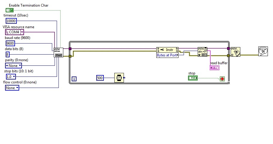
Could someone tell me if the Block Diagram is correct?
Any help is greatly appreciated.
I do not know anything about Labview, but I do not see the command you are sending to the Maestro anywhere in your diagram. Can you tell us exactly what bytes you are trying to send and what response you expect? You might want to try it first with the Pololu Serial Transmitter.
Thanks Paul,
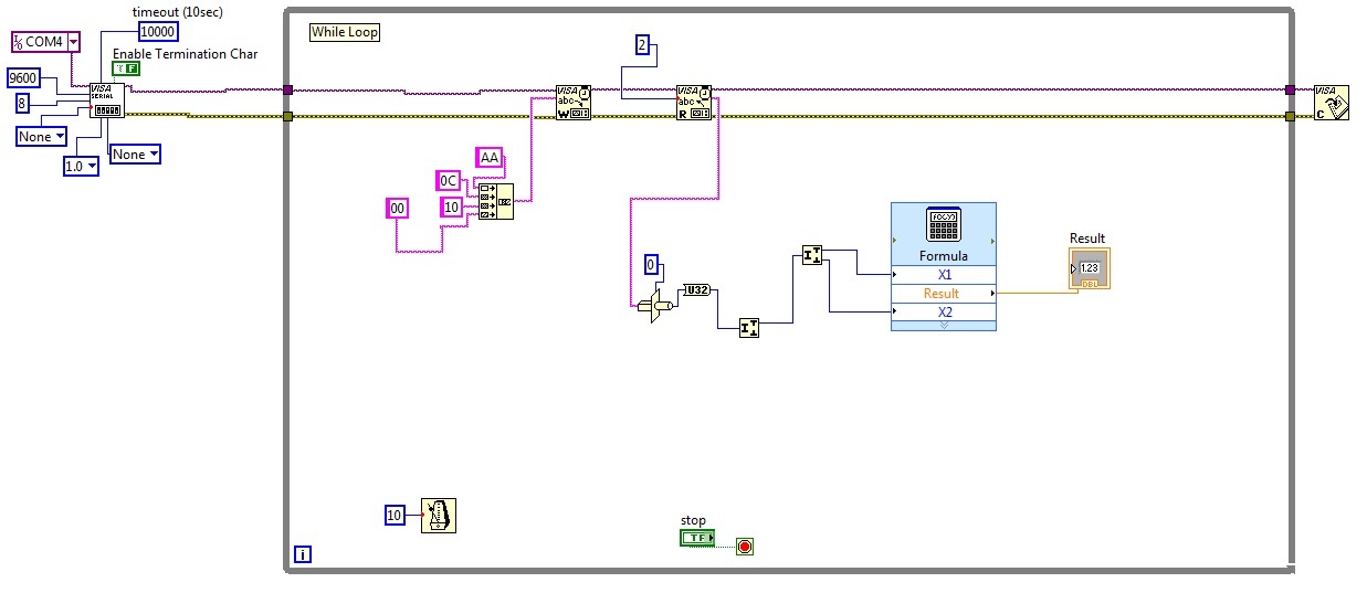
I found the way to read the input and I have added the block diagram for people in the same situation as I was.
Now I got another problem.
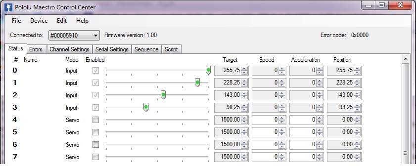
I need to read four sensors for my project. In the Maestro Control Center I configured the “channel 0” as an input and everything worked fine. If I configure the first four channels as inputs and if I connect only one of them to the sensor, the input voltage affects in the other channels position value. I have connected the voltage input only to channel 0 but the channel 1 2 and 3 are also moving (see in the following picture). They should be in 0 position due to the no input voltage.
Do you know what could be the reason?
The Maestro (like most microcontroller-based products) has a single analog-to-digital converter (ADC) that is switched between the different inputs. So, when it switches to a channel with nothing connected, the residual voltage left over from the previous channel will affect the reading.
This is not a problem, because once you actually connect something to those channels, they will work fine.
Also, I should say that “no input voltage” is quite different from “zero input voltage”, so you did not have any reason to expect them to be zero. If you really want your channels to be at zero when nothing is connected, you need to add a pull-down resistor.
Hi Jacogba-
I’m working on my own code in Labview for the 12 channel Maestro board and was wondering what protocol you communicated to the board with in Labview in order to get the input from the sensors. Do you think you could post a file of your code so I could try it?
Thanks,
Adela