Prop1 with Motor Controller Hookup HELP!

Hello. I purchased a Pololu Micro Dual Serial Motor Controller and I still have not been able to make the controller or this configuration work.

I may have supplied too much voltage (12V) and thereby damaged the controller.

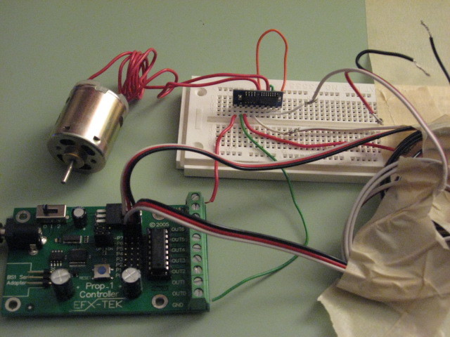
Please see included code, attached picture, and picture notes and help me answer the question… should this work??? and what WILL work??? I am new at this so please be specific about connection advice.


PICTURE NOTES:
EFX-TEK Prop1 Controller with BasicStamp1
3-pin Connection 6 - RESET, jumper in UP position
3-pin Connection 7 - LOGIC SUPPLY and SERIAL CONTROL INPUT, jumper in UP position
ULN 2003 installed. No ULN on Connection 7 (should there be NO ULN at all??)
Connection 6 “W” - reset
Connection 6 “R” - ??? I dont know where
Connection 6 “B” - ??? I dont know where
Connection 7 “W” - serial control
Connection 7 “R” - logic supply
Connection 7 “B” - ??? I dont know where(grounded?)
V+ had 12V (should there have been a simple resistor in series to drop the V to acceptable level?)
Motor Controller Pins 6 and 9 to positive motor
Motor Controller Pins 7 and 8 to negative motor


CODE: this code simply makes the motor speed up and slow down in one direction… then speed up and slow down in the other direction…

'   {$STAMP BS1}
'   {$PBASIC 1.0}
'
' =======================================================
' -----[ I/O Definitions ]-------------------------------------------------
SYMBOL  TX              = 7                     ' SETUP = UP; no ULN
SYMBOL  MReset          = 6                     ' SETUP = UP; no ULN

' -----[ Constants ]-------------------------------------------------------
SYMBOL  IsOn            = 1                     ' for active-high in/out
SYMBOL  IsOff           = 0
SYMBOL  Yes             = 1
SYMBOL  No              = 0
SYMBOL  Baud            = T2400

' -----[ Variables ]-------------------------------------------------------
SYMBOL  speed           = B2

' -----[ Initialization ]--------------------------------------------------
Reset:
  PINS = %11000000                              ' clear all
  DIRS = %11000000                              ' set outputs

  PULSOUT MReset, 1
  PAUSE 100

' -----[ Program Code ]----------------------------------------------------
Main:
  FOR speed = 0 TO 127
    SEROUT TX, Baud, ($80, $00, $00, speed)
    PAUSE 20
  NEXT

  FOR speed = 127 TO 0 STEP - 1
    SEROUT TX, Baud, ($80, $00, $00, speed)
    PAUSE 20
  NEXT

  FOR speed = 0 TO 127
    SEROUT TX, Baud, ($80, $00, $01, speed)
    PAUSE 20
  NEXT

  FOR speed = 127 TO 0 STEP - 1
    SEROUT TX, Baud, ($80, $00, $01, speed)
    PAUSE 20
  NEXT

  GOTO Main


Hello.

What is the ULN 2003? What do the jumper up positions mean?

The 12V motor supply is definitely a problem. It is possible that that damaged the motor driver, but the bigger problem going forward is that it’s not easy to change the 12V to something lower. The resistor divider you mentioned would not work (unless you use some big power resistors, and then you’d be wasting a lot of power). Can you use a different power source? If you really need 12V, you might consider the newer qik 2s9v1 dual serial motor controller.

Another potential problem is that you have the outputs connected together for single-motor mode; have you configured the motor controller for that? If not, you’re shorting two separate outputs together, which could also damage the device. What is your motor rating? At least for initial tests with no load, you can try without the two outputs paralleled, just to reduce the probability of a problem with the motor controller not being configured correctly.

I’m also a bit concerned about the wiring, which we can’t see all of in the picture. How long are the cables for the control signals? You should generally try to keep them as short as possible.

- Jan

Hello… here is a description of the 2003:
Seven-channel NPN Darlington array used to interface logic ciruits (i.e., microcontroller) to high-voltage, high-current devices like lamps, relays, and solenoids. The ULN2003A is capable of driving 500 mA into a single channel, up to 250 mA per channel with four channels active, and up to 150 mA with all seven channels active. ULN2003A outputs use clamp diodes for transient suppression to protect low-power microcontroller circuitry.

****The ULN2003A is the replacement for the ULN2803A when using P7 for serial communications.

The “jumpers” are the pull down/pull up resistors available on the 3-pin servo headers P6 and P7. Here is the Prop1 product description:
efx-tek.com/downloads/prop-1_docs.pdf

I’m not sure how to configure the motor controller for one-motor mode. I thought a simple line of code in the program does that.

Theres nothing else in the picture… those cables for the control signals are just wound up and taped off to the side. They are about 8 inches long.

I hope this helps. Thanks.

You don’t need the jumpers there, but if you’re going to have them, the up position is good. You don’t need the transistors for connecting to the motor controller. If you’re not connecting to the terminal blocks (which you shouldn’t), I suspect it doesn’t matter whether you have the chip plugged in or not.

The instructions for configuring the motor controller for single-motor mode are in the user’s guide. It is easy to do, but I didn’t see any indication of your having done it. It’s also possible you’ve blown out one of the two drivers, so you should still try the two outputs separately instead of hooking them up in parallel.

- Jan