I am building an LED light controller for my aquariums, using an Arduino Uno, and the 755 motor controller. I built a hardware and software prototype using one LED (9V 1A), and it works fine.
When I try to use this with a 5A load or a 10A load, and with either 12V or the original 9V supply, the LEDS fail to light. Each time I bring the controller back to the original 9V supply, the single 1A LED works fine; the motor controller is not damaged. At this point, I’ve used 3 power supplies (9V, 12V, 12V) and three lighting systems (1A, 5A, and 10A). The only combination that works is the 9V/1A combination.
I’m setting the DIR line low, I’m resetting the 755 at system startup, and I’m monitoring the FF lines. The two 12V power supplies are already powering the 5A and 10A lighting systems, so they can handle the load. I have the capacitor wired across the 755, so I would hope that switching noise is not the issue.
Can you tell us more about your LEDs and loads? Do you have datasheets for them? Can you measure the V+ voltage while your LEDs are failing to light? Are the fault flags doing anything?
I’m not sure what to say about the LEDs. They are 10 watt, 12 volt, 1 amp devices. As such, they have very little inductive or capacitive load: I figure they’ll appear to be totally resistive. In any event, the motor drivers are designed to handle an initial current spike, even though I don’t believe that there will be one. No data sheets: eBay from China. But everything works fine when run directly from the power supply.
The power supply voltage when the LEDS fail to light is as described: either 9V or 12V, depending on which power supply I’m using.
I am not limiting the LED current in any way. The power supply can deliver the 5 or 10 amps that the LEDs need, and the motor driver is rated at 15 amps continuous, and 20-30 amps instantaneous. I do not see any reason to limit the current. And the motor driver is not displaying an errorflag.
Ryan:
When the LEDs failed to light, I measured the voltage across the power supply at 9-12V (depending on which power supply I am using). The voltage to the LEDs always measures zero when the LEDs fail to light, but I’m using a digital volt meter, which could not “see” a PWM signal reliably. I have a 'scope I could use. I often see a brief spike in LED voltage when I reset the Arduino.
There’s no reason to expect what you’re doing to work if it’s just an LED. LEDs need some kind of current limiting, which is probably done by your power supply in the scenario where you have the direct connection working. If your “lighting system” is some subassembly that has extra parts built in, we can’t really comment on it meaningfully without the details of the system.
When you have your LEDs connected directly to your power supplies (i.e. no motor driver in the system), can you measure the power supply voltage with your multimeter or oscilloscope? Also, can you use your oscilloscope to look at the power supply voltage (V+, not the motor driver outputs) when your motor driver is in the system with a 5 A or 10 A LED/power supply?
“There’s no reason to expect what you’re doing to work if it’s just an LED”. While I understand why you might say this, these devices are intended to run directly off of 12 volts, and need no current limiting. If you’re thinking of small, single LEDs, think again. The power supply is not limiting the current in any way. If I put one device across 12 volts, it draws 1 amp; if I put 5 devices across 12 volts (in parallel), they draw 5 amps. Think of them as resistors. My “lighting system” consists ONLY of LED devices in parallel. Period. They work fine when run directly from the power supply.
With one power supply, when I connect the LEDs (5 amp) directly to the supply, the voltage across the LEDs is 9.03 volts. When I connect the LEDs to the output of the motor controller, the voltage across the LEDs is 0.106 volts. At that same time, the voltage going to the motor controller is 9.03 volts. Do you want me to use the 'scope to look for waveforms, or just to measure voltages?
As I said in my previous post, if your “lighting system” is some subassembly that has extra parts built in, we can’t really comment on it meaningfully without the details of the system. If no current-limiting is needed, then you have some sort of more complex subassembly with built-in current limiting, and it’s difficult to provide much help without knowing more about what you’re using.
Given that you have an oscilloscope, you should definitely be using it to try to figure out what’s going on. I suggest you start by looking at your power supply voltage both with and without the motor driver in the system and move on to looking at all the other points of interest (e.g. motor driver signal inputs, motor driver motor, and motor driver fault lines). There might be things happening over very short time scales that you simply wouldn’t be able to see with a multimeter. Also, I think you should periodically check the output voltages of the motor driver with no LEDs connected to make sure the driver is still functional.
Oh, and I notice that you mentioned PWM in a previous post. While trying to get this to work, I strongly suggest you use a steady high signal on the PWM pin rather than complicating things with a PWM signal. You should be able to essentially remove the Arduino from the picture, which simplifies your system greatly.
Your suggestion to bypass the PWM and just pull the motor controller input up to 5V was very helpful. When I did that with the 1A load, the LEDs light up just fine. When I try to run the 5A load, the LEDs light up for perhaps 1/4 second, and then turn off.
Is this a useful clue? As always, the +V power supply voltage is still at 9 V.
Sorry it has taken me so long to get back to you: my scope died and I had to buy another. Amazing what you can get for $70 from China these days on eBay!
After some fiddling, I think the problem turned out to be that I had the +/- wires swapped, so I was driving the LEDs with the reversed voltage. Silly me. I’m including the rest of this message in case it is of any use to other readers of the forum.
My current test setup is the Arduino driving the Pololu motor controller with a PWM signal and driving a set of LEDs with the motor controller. These are test LEDs, not the LEDs on my fish tank, but they are identical electronically. I started out with a load of one LED (9 V, 1 A), and when that worked, I added LEDs until I had 5 (9 V 5 A). It all works fine. I’m sending out a test pattern of 2/255, 4/255, 6/255, and 8/255 for light intensity: it ramps up and then drops down and ramps up again. So, the good news is that the motor driver is successfully driving the test LEDs
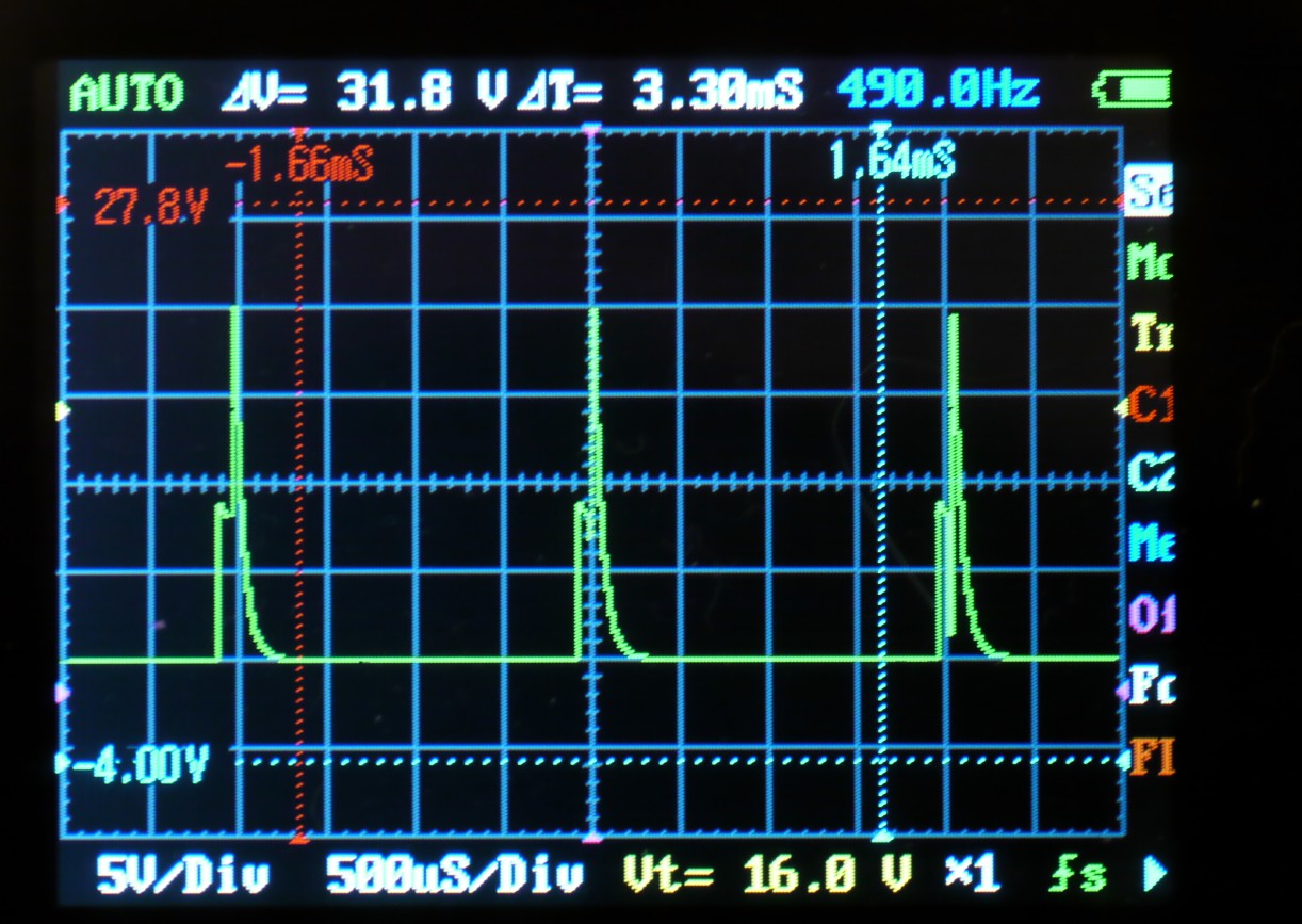
if you look at jonbondy.com/P1020655a.JPG you will see the PWM signal that is arriving at the string of 5 test LEDs. The thing that surprised me was the huge spike of positive voltage at the trailing edge of the pulse. This spike is almost 20 V on a system with a 9 V power supply! There are no capacitors or inductors in the circuit, other than the capacitor you supplied to filter the power at the motor driver.
For comparison purposes, see jonbondy.com/P1020656a.JPG which shows the PWM signal that I am using to drive the same LEDs in my kitchen, but using a regular PWM light dimmer (not from Pololu).
Note that the 5 test LEDs are all on a single 12" heat sink, while the 12 LEDs in the kitchen are on 7 separate light fixtures/heat sinks with wires that probably are a total of 20 to 25 feet in length. That is, the kitchen wiring is long and distributed, while the test LEDS are wired very compactly. The strange thing is that the signal for the kitchen LEDs is relatively clean, while that for the test LEDs has that ringing spike. Any idea what might be causing that spike, whether I should try to eliminate it, and how?
I apologize for the long delay. I don’t really have a good sense of your system; can you please post a schematic and possibly a picture of your setup? Just to be clear, it works with the test setup but you are concerned about the quality of the signal? Do these test LEDs have built-in current limiters? What are you using for your power supply?
Sorry for the delay. I finally gave up on the power supplies I was using for the fish tanks, and bought different ones. They are now in service, and both fish tanks and lighting systems appear to be working flawlessly, without any changes to the electronics.
So, I guess the take-home message is to be careful about the power supplies.
