Pololu Micro Maestro 6, power supply

Hello,

I was trying to use Micro Maestro 6 to build a simple light shutter. Following the page 90 in the manual (https://www.pololu.com/docs/pdf/0J40/maestro.pdf), I directly powered the board with USB, and the LED indicators look normal, and the communication software also looks normal.

However, the multimeter read value on Vin is very close to 0V. When I used a jump wire to connect Vin and Vservo, servo cannot run by using the software.

Could anyone give some suggestions? Thanks!

Hello.

It is normal for the Maestro’s USB power to not be available at the VIN pin due to the power switching circuit (they are both inputs). However, it sounds like you are trying to power the Maestro and the servos from USB, which is not one of the methods shown in the Powering the Maestro section of the user’s guide that you’re referring to. you might be trying to combine the first method (powering the Maestro from USB and the servos from a separate power supply) and the third method (powering the servos from a separate power supply and using a jumper to power the Maestro through VIN). For reference, USB ports can typically only source around 500mA, and a good rule of thumb is to budget around 1A for a single standard-size servo. If the servos tries to pull more than 500mA, it could cause damage to your USB port (or worse).

Ultimately, if you want to power the Maestro’s logic side through USB (the first method), I recommend using a separate power supply for the servos. If you want to use a single power source (the third method), you should use something more appropriate than USB, such as a wall power adapter or batteries.

Brandon

Thanks Brandon!

I now connect the servo controller with an external power, and the servo can be controlled by Pololu Maestro Control Center.

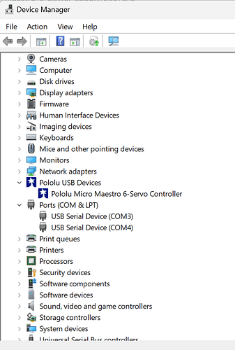
My goal is to control the servo controller via COM ports by using Matlab. However, from Windows 10 Device Manager, I see Maestro-6 under Pololu USB Devices, but not COM ports. How should I configure it, so that it can be accessed via COM ports?

Or with the current configuration, is there any convenient way of controlling it using Matlab?

Those “USB Serial Device” entries are probably for your Maestro. They can appear this way when Windows sets up your Maestro using the default Windows serial driver (which can happen if you plug the Maestro in before installing our drivers for it). The ports are still usable like this, but since it is hard to distinguish the ports from each other, we recommend fixing it by right-clicking on each “USB Serial Device” entry, selecting “Update Driver Software…”, and then selecting “Search automatically for updated driver software”. If it works, you should see one entry for the command port and one entry for the TTL port.

We do not use MATLAB, so I do not have any specific advice for using it to control the Maestro, but you can use the short MATLAB example code in this post by David for reference. Please note that you will need to set the Maestro’s serial mode to USB Dual Port and be sure to use the Maestro’s Command Port.

Brandon

I used Matlab Instrument Control Toolbox, and below is my code. However, the code cannot drive the board to output the signal, could anyone help check if my command signal is correct or not?

I used an oscilloscope to check the last port (port 5, index starts at 0) for my Maestro 6. When I use the Pololu Maestro Control Center, the port will output a periodic square wave, with duty cycle being adjusted when I drag the bar left and right. However, when I switch to Matlab, the oscilloscope values always read at 0.


DCMotor = serial(‘COM3’,‘Baudrate’,9600,‘DataBits’,8,‘Parity’,‘none’,‘InputBufferSize’,16384);

fopen(DCMotor); %Open the motor

%% Maestro 6 controller

fwrite(DCMotor,170,‘uint8’) %Initialize the Motor

pause(0.1)

fwrite(DCMotor ,[132,5,112,46],‘uint8’); % write to port 6th port (0,1,2,3,4,5), Compact protocal

txdata = [‘AA’;‘06’;‘04’;‘05’;‘70’;‘2E’];

%Convert to decimal format

txdata_dec = hex2dec(txdata);

%Write using the UINT8 data format

fwrite(DCMotor,txdata_dec,‘uint8’); % Pololu protocal

%%

fclose(DCMotor); %Close the motor

Your bytes for the compact protocol command ([132,5,112,46]) look okay to me and should set channel 5 to 1500µs.

For your Pololu protocol command ([‘AA’;‘06’;‘04’;‘05’;‘70’;‘2E’]), it looks like you’re using a device number of 6. Please note that the default device number for the Maestro is 12, so it will only respond to this command if you have changed the device number to 6, which you can do from the “Serial Settings” tab of the Maestro Control Center.

By the way, you might find our Serial Transmitter Utility helpful for testing your commands separately from your MATLAB program.

If you’re still not able to get the Maestro to respond, I recommend double checking that it serial mode is configured as “USB Dual Port” and confirm your device number matches for the Pololu protocol.

Brandon

1 Like

A separate question regarding Sub-Micro Servo 3.7g.

What is its peak current when rotating at full speed/acceleration? I’m trying to use a computer USB to power it up, and the port output is 0.5A limited.

It sounds like you’re referring to our #1053 Sub-Micro Servo 3.7g. Unfortunately, the manufacturer does not make any specific claims about the maximum current. Since voltage and current are proportional, you might try briefly stalling your servo at a low voltage while measuring the current, then extrapolating to what it would be at 5V. However, I generally wouldn’t recommend powering devices like servos or motors from a computer USB, since even if they aren’t expected to draw more than 500mA during normal operation, a failure could result in much higher current draw and potentially damage your computer. Also, quickly switching directions at high speed can cause a spike that’s upwards of twice the rated stall current.

Brandon

FYI.

I did a current measurement (servo motor current only, not including the Micro Maestro 6 controller, 6V DC input) for servo motor #1053 Sub-Micro Servo 3.7g at certain speeds with no acceleration limit, moving the servo position from one end to the other.

Speed / Current (mA)
8 / 34
16 / 37
32 / 47
48 / 56
64 / 65
80 / 73

From the data, the motor itself sucks about tens of mA at my speed range. It seems that a typical USB port (500mA max) from laptop could be sufficient to drive the servo at relatively low speed. I would guess the Micro Maestro 6 controller takes tens of mA current, and in total the Motor and Controller together should be able to be powered by a typical USB port.

Don’t forget that “stall current” can be much higher than “running at speed current”