I’m building a automated camera pan an tilt platform to take panorama pictures. I don’t have much electronics experience but I’m jumping in the deep end anyway
I’m trying to connect my LV168 with the Micro Serial Servo Controller.
As far as I can figure out the serial lines on the LV168 are PD0 and PD1, are these the user I/O lines 8 and 7?
So should I connect:
(on LV168) - (on servo controller)
User I/O signal 7 - RS232 serial input
User I/O ground 7 - GND
Are there by any change example programs for the LV-168 that demonstrate the micro servo controller?
Hey Marcel, it’s not quite the same as your setup, but have you taken a look at this thread?
Anyway, you want to connect PD1 (I/O pin 7) to the logic-level serial input (SIN) pin on your micro serial servo controller, not the RS-232 level serial input pin. Also, you must have a ground connection between the two devices, but which ground pin you use isn’t of particular importance.
As for a code example, if you want to use the Arduino language, that thread I linked to above should help. If you’re writing in C, this should work, but I hate posting code I haven’t actually tested:
#define F_CPU	20000000//CPU clock
#define BAUD	9600//baud rate for UART
#define MYUBRR	129//(F_CPU/16/BAUD-1) baud rate variable for UART hardware

#include <avr/io.h>

void USART_Init(unsigned int ubrr);
void USART_Trans(unsigned char data);

int main(){
	USART_Init(MYUBRR);

	USART_Trans(0x80);//start byte
	USART_Trans(0x01);//device ID (servo controller)
	USART_Trans(0x04);//command number 4 (absolute position)
	USART_Trans(0x00);//servo number
	USART_Trans(0x17);//position high bits
	USART_Trans(0x38);//position low 7 bits

	while(1);
}

void USART_Init(unsigned int ubrr){//Initialize USART hardware
	UBRR0H=(unsigned char)(ubrr>>8);//set buad rate
	UBRR0L=(unsigned char) ubrr;
	UCSR0B=(1<<TXEN0);//enable transmitter
	UCSR0C=(3<<UCSZ00);//Set frame format for 8bit with 1 stop
}

void USART_Trans (unsigned char data){//Transmit a byte of data over USART
	while(!(UCSR0A&(1<<UDRE0)));//wait for transmition to complete
	UDR0=data;
}
That should set servo 0 to its neutral position, using Pololu mode (mode select jumper removed on the servo controller) with the LV168 running at full 20MHz. Is everything working now?
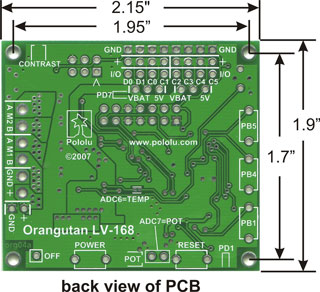
I assume that by “user I/O lines 7 and 8” you mean counting the header pins from left to right on the LV-168 starting from 1? If so, then you are correct. If you look on the silkscreen on the back of the board you can see the serial pins labeled as D0 and D1:
So when the board is flipped over and you’re looking down at the top side of the PCB, the LV-168’s serial receive pin (PD0) is the rightmost one on the 3x8 header strip, and the serial transmit pin (PD1) is the one just to the left of it.
Is using the connection from PD7 (ground+signal) to the RS232 not possible?
The reason I want to use the RS232 input is because the LV168 and the Servo controller are using diferent voltages. The LV168 is using 3.6V and the Servo Controller is using 4.8V.
I tried your example program, but unfortunately it doesn’t seem to work. I see the following:
(Both LV168 and Servo Controller are off)
Turn on Servo Controller → Yellow LED is on continously
Turn on LV168 → Red LED is on continously, green LED blinks
Could this be because I’m using the RS232 input?
I tried hooking up the LV168 to the same battery pack as the servo controller (4 x 1.2V) but it then the LV168 made a high pitched squeaky sound, so I turned it off directly. It didn’t sound healthy at all.
The Orangutan LV168 is actually running at 5V (it uses a step-up voltage regulator to produce 5V from source voltages as low as 2V), so it can communicate just fine with the micro serial servo controller.
The serial output of the LV168 must be connected to the logic level serial input pin of the servo controller, the RS-232 input will invert the serial signal, which is probably why you saw the servo controller’s LEDs indicating a serial error.
I hope your LV168 is alright, you should never connect more than 5V to it. The rating of your battery pack is the “nominal” voltage, but the voltage actually varies as the battery is charged and discharged. A fully charged NiMH four-cell pack can reach 6.4V, well out of spec of the LV168.
Also, just to check, are you using the VCC=VS jumper on your servo controller? This bypasses the on-board voltage regulator, so you should not apply more than 5V this way. Good power options are:
How’s it going now? Did your LV168 survive?
Ah, I didn’t know that! Luckily it seems my LV-168 did survive, first thing I did was reprogram it with the test program. To my relief it seems to work ok (funky music!)
I tried hooking up the Servo controller to the 3 cell battery pack, but it doesn’t seem to have enough power that way. When I use 4 cell pack the yellow LED is on as soon as I connect, when I use the 3-cell pack none of the LEDs turn on. (Or are all LEDs supposed to be off?)
That leaves me with the problem on how to lay the ground wire between the two boards. Here is my current setup (without a GND wire, so it won’t work):
Laying a GND wire between the GND pins on the two board seems like a bad idea, since they are on different voltages. Or isn’t that a problem?
I don’t see the image in your post (I just see the word “image”) but yes, you will need a ground wire connecting your two boards, and no, it won’t be a problem if they’re at different voltages. The ground connection just serves as a reference for the signal power. Voltages aren’t absolute, they’re relative differences, so the signals sent from your Orangutan to your servo controller need a common reference (i.e. 5V more than what?).
Also, since the electronics on the servo controller are powered through a 5V linear regulator (which limits higher input voltages down to 5V) and the electronics on your LV168 Orangutan are powered through a step-up regulator (which increases lower voltages up to 5V) the two boards are actually ‘running’ at the same voltage anyway, even though they’re being powered from different sources.
Actually, the LV168 5V step-up regulator can source about 150mA above what the Orangutan uses itself, and the servo controller’s regulator can take 5V as its input. If you’re not doing anything else with it, you could power the electronics of your servo controller (voltage input on the left side of the board in the pictures) from the LV168’s 5V output header, and the servo bus (right side of the board in the pictures) from a separate, higher battery. Just MAKE SURE you don’t have the VCC=VS jumpers connected!
I’m back at it after a break, and connecting the ground wire has worked! My servo is making tiny ticking noises indicating that its getting some signals at least. Not much movement though.
Sorry to have to ask help again, but which values should I send to make it ping-pong between the maximum values?
I tried something like this:
    int main(){

	USART_Init(MYUBRR);

       while(1){

       USART_Trans(0x80);//start byte
       USART_Trans(0x01);//device ID (servo controller)
       USART_Trans(0x04);//command number 4 (absolute position)
       USART_Trans(0x00);//servo number
       USART_Trans(0x17);//position high bits
       USART_Trans(0x38);//position low 7 bits

	   _delay_ms(1000);

	USART_Trans(0x80);//start byte
       USART_Trans(0x01);//device ID (servo controller)
       USART_Trans(0x04);//command number 4 (absolute position)
       USART_Trans(0x00);//servo number
       USART_Trans(0x17);//position high bits
       USART_Trans(0x34);//position low 7 bits

	   _delay_ms(1000);

	   }
    }
Hey Marcel, welcome back. I see two little bugs in the code you pasted above.
First, you had no way of knowing this, but at a 20MHz clock speed the stock _delay_ms function maxes out at 13ms, so your second-long delays are really only 13ms long. You can achieve longer delays by calling a shorter delay multiple times in a loop.
Also, the two different positions you’re commanding are very close together, since you’re only changing the low byte of the two-byte absolute position command. The two-byte protocol has a range from 500 to 5500, so on a scale with 5000 increments you’re commanding a change of only 4 increments. Frankly I’m surprised the servo is even making noise for such a small change.
You don’t want to slam your servo into its mechanical stops, so lets try swinging it between 2000 and 4000. Using the Pololu mode absolute position protocol, the two position bytes would be:
2000: 0x0F,0x50
4000: 0x1F,0x20
So you would want to change your code to something like this:
int main(){

	USART_Init(MYUBRR);

	unsigned char i;

	while(1){

		USART_Trans(0x80);//start byte
		USART_Trans(0x01);//device ID (servo controller)
		USART_Trans(0x04);//command number 4 (absolute position)
		USART_Trans(0x00);//servo number
		USART_Trans(0x0F);//position high bits (2000: 0x0F,0x50)
		USART_Trans(0x50);//position low 7 bits

		for(i=0;i<100;i++){
			_delay_ms(10);
		}

		USART_Trans(0x80);//start byte
		USART_Trans(0x01);//device ID (servo controller)
		USART_Trans(0x04);//command number 4 (absolute position)
		USART_Trans(0x00);//servo number
		USART_Trans(0x1F);//position high bits (4000: 0x1F,0x20)
		USART_Trans(0x20);//position low 7 bits

		for(i=0;i<100;i++){
			_delay_ms(10);
		}

	}
}
Did that do it? For a little more explanation of the Pololu-mode absolute position protocol, check out this thread.
I’ve added a bit of code that prints to the lcd, the program is running fine switching the position ever second.
The green led on the Servo controller is blinking every 1 sec, but the servo is not moving.
I’ve also tried a different servo (the one I’m using is the huge HiTec 805BB) but that gave me no movement either. The batteries are fully charged.
Thanks again for your help, I really appreciate that you are taking your time to help me out here. Once I get the servo moving I’m sure I do the rest myself
Hmm, that all looks right. Have you tried checking the servo number settings? Sometimes in figuring out how to use the servo controller, you can accidentally send a string of bytes that configures the controller to respond to a different set of servo numbers (I’ve done it).
Detailed instructions are in the manual, but basically you can check the servo number range by putting the servo controller in Pololu mode (pull off the jumper then start it up) and sending the byte string {0x80, 0x02, 0x10}. The red and yellow LEDs should turn on, and the green led should flash a number of times over and over again with a 1 second pause in between. If the green LED flashes just once that’s not the problem, but if it flashes any other number of times the servo number range has been changed. To reset it to normal (servos 0-7) reset the servo controller and send it the byte string {0x80, 0x02, 0x00}. You should now see the green LED flash just once every second. You’ll need to reset the servo controller again before it will move any servos.
It works! My servo is happily moving back and forth.
I’m ashamed to say the problem was that I had the Servo Controller in Mini SSC II mode, I thought the jumper was to turn Pololu mode on…
Many thanks for your help, I’ll be sure to post once I have some practical results out of my camera rig (or when I have more questions, which is more likely )


 )
)