You should be able to get useful readings from that sensor. Note that you will not be able to measure very small currents accurately, however: your resolution is around 25 mA. Things should get better if you command your motor to move faster and try to stall it, since the stall current will be higher. Also, you should try averaging a few current readings together using:
thanks for your help. with the analog_read_average_millivolts function i get more stable and meaningful values, even at small motor speeds -thats exactly what i was looking for! thank you! so i will also have a more stable night tonight (its 8pm in my home-country now;-)
sorry, one more question about the current sensoring:
because i´m using my motor on a very low voltage this sensor seems to be a bit too inaccurate. (you spoke about a resolution of 25mA). can you tell me something about the onboard current sensor of the orangutan with VNH2? is it compareable to one of the standalone current sensor? or is it “universal” with a controllable range of accuracy? is there a documentation about this onboard sensor?
…but i think, with your help of course, i´m on the right way now…
The built-in current sensor on the VNH2SP30 is worse than the one you have now. It has a sensitivity of 130 mV/A, which would give you a resolution of around 40 mA. You can look at the VNH2SP30 datasheet for more information. Keep in mind that the VNH2SP30 and VNH3SP30 drivers are capable of delivering up to 30 A, so there are very few applications where you would want to use such a powerful driver while being able to accurately measure something as small as a few milliamps.
The highest-sensitivity external current sensor we carry is the ACS714 Current Sensor Carrier -5 to +5A, which provides 185 mV/A (this isn’t a major improvement over the 167 mV/A of the sensor you are using now).
Maybe you could consider using our Orangutan SVP. It has motor drivers that can deliver a continuous 2 A (6 A peak) and integrated current sensors with a sensitivity of 850 mV/A (which corresponds to a resolution of around 6 mA). It also has inputs for two quadrature encoders along with a secondary processor that can read the encoders for you. It sounds like this controller, which happens to be our newest Orangutan, is better suited for your current project.
it sounds interesting for me that this carrier sensor is more sensitive. just one question to the SVP: what do you think about the lifecycle of such controllerboards in general? can you imagine that such a board is used over 10 years? and what about the influence of higher current? do you think the board will live longer if the current is lower in relation to the max. A?
for example: i´m using 2 motors on my board, one is quite low-current (thats the one we talked about in the whole last postings). but the other one is driven by 300mA freerun and 5A stall, that would be exact good values for the SVP. i think in real life usage it would run exactly at the 2A the SVP allowes. so what do you think about that? does that influenc the lifetime of the SVP? is it better for the board lifetime having a X2, because its quite low-current for that controller?
We have not characterized the lifecycle of these parts, but I expect them to work for many years as long as you use them in spec. The VNH3SP30 motor drivers are probably more robust than the TB6612FNG drivers used on the Orangutan SVP, so at least the motor driver circuitry of the X2 will likely be more forgiving of mistreatment than the motor driver circuitry of the SVP. However, the SVP may not be appropriate for your application if you really plan on being right at the top of its 2 A continuous current rating. I don’t expect this to significantly shorten the SVPs life; rather, the problem could be that it often inconveniently goes into thermal shutdown because you’ve overtaxed the driver.
ok, so perhaps it would be a solution for me to take another motor.
when i have an average current of not more than 1A you could recommend the SVP?
could you please tell me something about the programming procedure? can i say that programming via usb interface and AVR Studio works similar to the X2? in the online documentation there is mentioned a auxiliary processor which can be programmed via usb?
Basically, you should pick a driver that can handle your peak needs. If your motor draws 1A 90% of the time, but occasionally you need to be able to supply 3 A for a minute, the SVP is probably not appropriate, because it will likely overheat during that minute of 3 A draw. I suggest you pick a motor driver that can handle your peak needs and at least gives you a bit of a margin above your typical needs.
Programming the SVP is very similar to programming the X2. Both have integrated programmers, so all you need to do is plug it into USB. While the X2 has a programming mode (you need to hold the reset button for 0.5 s to put it in programming mode), the SVP just has multiple virtual COM ports, one of which can be used for programming and the other for general-purpose serial communication. All you would do is select the SVP’s programming com port from your programming software.
finally i have bought and set up a orangutan svp. now i have again problems with reading the current sensor values. i am not really sure about my hardware setting.
i wrote the following code:
motor 1 is running, so the connection and the code is correct. but what about the current sensing? i connected the M1 current sense to the A0 I/O pin. when it is plugged in, i get the value “0”, when i plug it out, the lcd says “1579” , sometimes changing a little bit. i didn’t change any wiring/jumpers on the SVP, it’s like i bought it.
ok, the wiring is correct, because when i try higher motor speeds, it works. the problem is, that i thought, the current sensor of the svp is accurate enough to handle such small differences like stalling my motor at a motor speed of 30. is there a possibility of getting mor sensible measuring with this sensor? when i increase the speed to 60 the sensor goes to “5”, when i stall it, but i really need a meaningful change of its value at a speed of 30…
70 mA free run and 360mA (nearly) stall → thats exactly the point where the LCD is changing from “0” to “5”. when these values really are millivolts, there must be a value around 60 (according to your description of the onboard current sensor). am i right? what am i doing wrong?
Can you stall your motor at full speed (i.e. 255) and measure the motor current with your multimeter, and then repeat the exact same test except this time use your multimeter to measure the voltage on the appropriate CS output (with the CS pin disconnected). I’d like to get a sense for exactly what voltage the pin is outputing at what current.
yes, here are my results (measured with multimeter):
current: 1930 mA stall
mV at the current sensor:
motor speed mV free run mV stall
30                  2.2                   2.3
60                  2.3                   40
255 45 1600
when i do the same measurement on motorport2 /CS2, the values are quite different:
motor speed mV free run mV stall
30                  66.2                 78
60                  82.1                155
255 45 1900
at motor speed 0 on both ports CS1 shows 1mA and CS2 65mA.
as you can see the values are quite different on the two ports. is that on purpose? i don’t think so. is there a way to calibrate the CS? in the second case it seems to me that the changing of the values is significant enough for my setting. but i need to reproduce my settings a few times. so i am not sure if i can rely on that value. do you think those different behaviors of the two sensor outputs is similar on every SVP or is it possible that sometimes the values are similar, sometimes both as insignificant as my CS1? i am a little disappointed about that, because i bought the SVP exactly because of its more accurate CS…
I looked into this a little more to make sure there wasn’t an error in our SVP product description. It seems that the op-amp used to amplify the current sense voltage has an offset error that is typically 1.7 mV and can be as high as 7 mV. The gain is 34, which means the current sense output can be offset in either direction by up to around 250 mV.
The slope of the output is very close to the specified 850 mV/A, but you need to empirically determine what offset needs to be applied to the CS output in order to accurately convert it from voltage to current. If the offset is in one direction, you will see a non-zero CS voltage even when the current is zero (it sounds like this is the case with your motor port 2). If the offset is in the other direction, the CS output voltage will be zero until the current overcomes the offset (it sounds like this is the case with your motor port 1). It sounds like maybe you should try using motor port 2 for what you are trying to do.
Note that you can minimize the impact of this offset by making the SVP’s current sense more sensitive. By default, it uses two 0.05 Ohm resistors in parallel to make a 0.025 Ohm current sense resistor. This produces CS pin output voltage of approximately 5 V when the motor current is 6 A (the peak current the SVP’s motor driver can deliver). If you are sure you will never need more than 3 A from the motor driver, you can knock one of the two 0.05 Ohm current sense resistors off, making the CS output twice as sensitive. Alternatively, you could replace the CS resistors entirely with something larger, like a 0.1, which would quadruple the sensitivity (but limit you to 1.5 A). If you want to try this and need help identifying the current sense resistors, please let me know.
YESSS, that sounds very good- i need one high power motor port and the other one with 2A max and more sensible CS. Please teach me how to make CS2 twice as sensible…
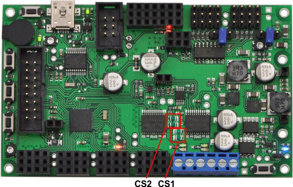
The current-sense resistors are the big green ones I highlighted in the above picture. The upper pair measures M2 current and the lower pair measures M1 current. You should decide which one you want to use for your low-current sensing (it should probably be CS2, since the offset on this port doesn’t appear to interfere with your ability to measure low currents) and desolder one of the two resistors for this motor channel. You can do this with a soldering iron by alternately heating the two sides of one resistor, switching every second or so, until it comes loose. Be very careful not to accidentally knock off other components while you’re doing this. Also, you might want to save the resistor somewhere so you have the option of putting it back later if you want to.
You should leave it disconnected. If you bridge the two pads with a wire, you are creating a short past the remaining resistor and effectively making the current sense resistance zero, so you would get no CS feedback.
The resistors I highlighted for you are R12, R13, R18, and R19 in the SVP schematic. To make the CS feedback more sensitive, you need the CS resistor to be bigger. By removing one of the parallel resistors, you are effectively doubling the resistance.