
I have a couple of sensors I want to hook up to the X2, and they both operate at about 3V. It looks like the X2 makes 5V available, but not 3V. Do I need to set up some kind of voltage divider to convert the 5V to a 3V output for my sensors, or is there an easier way? Thanks!
What sensors specifically do you want to use?
In general, yes, you don’t want to feed 5V into a 3.3V device, especially power, but also not even if it’s just a signal line. There are some simple workarounds, especially with AVRs, which have nice low thresholds for registering a digital line as ‘High’ (running at 5V, an AVR will typically register a 3.3V input as high).
How to do it really depends on the communication protocol used by the device. For example, it’s super-easy to interface a 3.3V sensor with a 5V AVR over I2C. SPI is a little more involved, but its still totally doable.
You may also run into a little difficulty making the necessary connections to interface digital sensors with the X2. The Hardware I2C lines of the ATMega644 go to the LCD header, although you still might be able to use both at once. The I2C lines of the ATMega168 are used for other things, and not really available at all. The two AVRs on the X2 use their SPI hardware to communicate with eachother, but with a couple of tweaks you can add more devices to the SPI bus.
You can also fake these protocols in software and use whichever pins you want, but of course it’s better to use hardware to handle the overhead.
-Adam
Triple Axis Accelerometer Breakout - LIS3LV02DQ
Gyro Breakout Board - Dual Axis IDG300
The accelerometer apparently has an I2C interface, so I guess I should use that. What’s the 3V workaround for I2C?
As for the gyro, I just realized it doesn’t seem to have a digital interface at all. I guess I can hook it up to one of the 8 analog inputs on the X2, right? What’s the workaround for 3V in that case?
Small world, I’m using that exact accelerometer with a Baby Orangutan in a robotic helicopter project, and I’m playing around with the Sparkfun 5DOF IMU that uses that same gyro. I can post my I2C routines tomorrow morning if you like. They set up the I2C hardware on the ATMega168 (which might need some tweaking to run on the ATMega644) and handle the basic functionality of initializing the LIS3LV02DQ and reading the X, Y, and Z values.
Anyway, the great thing about the I2C protocol is that both the serial and the clock lines are “open drain.” Basically both lines are pulled high by resistors, and the devices communicate by pulling the lines low:
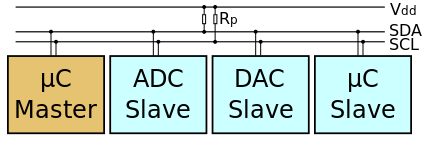
*Thanks Wikipedia!
No device on the bus ever drives the lines high, but any device can pull the lines low at any time. This lets any device on the bus pause communication while another device is talking by keeping the clock line low.
You can connect the grounds of your X2 and your accelerometer, and use two resistors (in the 1Kohm to 10Kohm range) to pull the clock and data lines up to 3.3V (i.e. the accelerometer power line). 3.3V is high enough to register on an AVR running at 5V, and since the AVR will only pull the lines low, it won’t damage your accelerometer by trying to send it 5V signals.
You will need to be careful not to set either of these pins to 5V high in your X2 program, which unfortunately means no using the LCD while the accelerometer is connected. If you look at the reviews for this accelerometer on Sparkfun, the first one is from a guy who tried to run it at 5V: “Not a 5V part. Ran on 5V and it worked for a few hours.” Now, he was trying to power it off of 5V. It will probably last longer if you only send it signals at 5V (like if you use the LCD briefly), but you’ll still be shortening the operating life. Incidentally, the second review is from me explaining this interface trick.
If you really want to use the LCD, but don’t want to slowly fry the accelerometer, you can implement the I2C protocol in software and use whichever pins you like. I don’t know of a good code to do that offhand, but one must exist.
As for the gyro, you should run it at 3.3V, connect its ground to the X2 ground, and measure the X and Y outputs directly with X2 ADC inputs. You won’t hurt it by measuring it this way, but you also won’t get the full 10 bit resolution, since the signal won’t go all the way up to 5V. You might also want to measure the gyro’s Vref voltage for comparison, since the two regulated voltages running the two devices may wander over time. You can (and should) protect the gyro from accidental high outputs of the X2 pins by putting current-limiting resistors in-line with all the analog connections.
-Adam
P.S. In a pinch, I think you can use the internal pull-up resistors of the AVR I/O lines to pull the I2C lines high instead of external resistors (I’m not 100% sure of this, can anyone confirm or deny?). That would pull both lines up to the AVR voltage though, so this isn’t a good trick to use when interfacing with a lower-voltage device.
Okay, I cleaned up my accelerometer test program. The code is a bit long so I just put the file here.
Basically it sets up the hardware I2C and USART, initializes the accelerometer, polls the accelerometer values (at full 12 byte resolution) 20 times a second, combines the bytes into an array of three signed integers (the X, Y, and Z accelerometer readings), and sends these values out the UART as ASCII text.
There are a set of comments you can remove to stop the continuous polling of the accelerometer, and instead have it poll and respond each time the AVR receives a character over the USART (i.e. when you press a key in the terminal program you’re looking at the data on).
I tested this code just now on an ATMega168 Baby Orangutan, and it works just fine. I can’t completely test it on my X2 since my accelerometer is pretty solidly integrated into my helicopter board. I think the code should only need one tweak to compile and run on the X2’s ATMega644, you should change the line:
ISR(USART_RX_vect){//USART Byte reieved
to read:
ISR(USART0_RX_vect){//USART Byte reieved
Don’t ask me why the vectors have different names, even though the register names are all the same. Also, keep in mind when running this code on your X2 that it’s using the hardware USART on the ATMega644. The USB to Serial adapter is connected to the hardware USART on the ATMega168. You should be able to copy in a couple of the Pololu library functions if you want to look at the accelerometer readings over the USB connection.
-Adam
P.S. The I2C hardware functions are based on code by Peter Fleury. If you’re interested in implementing a software I2C interface (say, to keep the LCD usable) it turns out Peter also has code for that on his page.
I’m still stuck just trying to get power to these sensors. (I’ll deal with signal line voltage later.) I started out constructing a voltage divider out of two resistors to drop my 9V 800mA source down to 3.3V. But then I read somewhere that a simple resistive voltage divider could cause problems (can’t remember what exactly) and that I should instead be using a proper voltage regulator.
So now I’m trying to figure out what voltage regulator I should buy, but I’m completely overwhelmed. There are literally hundreds of different 3.3V regulators listed on the Jameco and Digikey websites. How do I know which to choose?
Yeah, a resistor-based voltage divider is good for very low current, high impedance applications like generating a reference voltage for an ADC, but not for powering most devices. Depending on the net resistance you use you will either ALWAYS be wasting lots of power, or limiting yourself to far too little current, or both. Not to mention that the internal, relatively low impedance of your device will mess up the division factor. Basically you don’t use voltage dividers to power things.
Anyway, if you’re just ordering a voltage regulator or two, you should skip Digikey ($25 minimum order or $5 handling) and go to Jameco. You should still get a few and any other parts you think you need, why waste the shipping. The other things to consider are your source voltage and current requirements, chip package, and price.
If you’re going to be using a voltage source close to your output voltage (like 5V), you’ll need a low-dropout (LDO) regulator. For a 9V source, a regular (not LDO) regulator should be fine. Of course there’s also an upper limit to the voltage you can use with a given regulator, so keep an eye on that, but those should be in the 10V-50V range.
Then make sure it can supply enough current for your device. Your two sensors together only need about 10mA (if I’m skimming the data-sheets right) so just about any regulator will do.
Then pick a package you like. Do you want surface mount? Through hole? Are you going for microscopic, or something you can easily solder by hand?
After taking all these into consideration, I usually get the cheapest one left (both Digikey and Jameco have good drill-down type menus). Or you could just go out to Radio Shack. They don’t sell a 3.3V regulator, but they do sell an adjustable one (I think you set the output voltage with resistors, be careful!).
Good luck!
-Adam
I had emailed Jameco with a question a couple days ago, but they’ve yet to get back with me. In the meantime, Digi-Key has online chat customer service and was able to answer my questions right away. I think I can find $25 of other stuff to order, so I think I’ll go with Digi-Key.
Digi-Key told me that LDO basically means it’s a “better” regulator. The tech said that supply can dip lower to the output voltage than a non-LDO can without the ouput being affected. They suggested the LM2936Z-3.3/NOPB.