Need a bit of help with pwr distribution motor board for Romi

Hi all,

This is my first post. I have a Romi chassis with the power distribution motor driver board; however, I can’t get it to work. I have not located any user guides or tutorial that explains how the connections to the Arduino go.

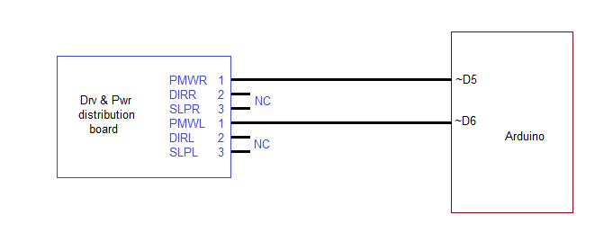
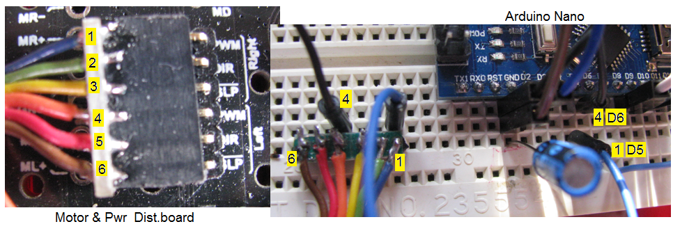
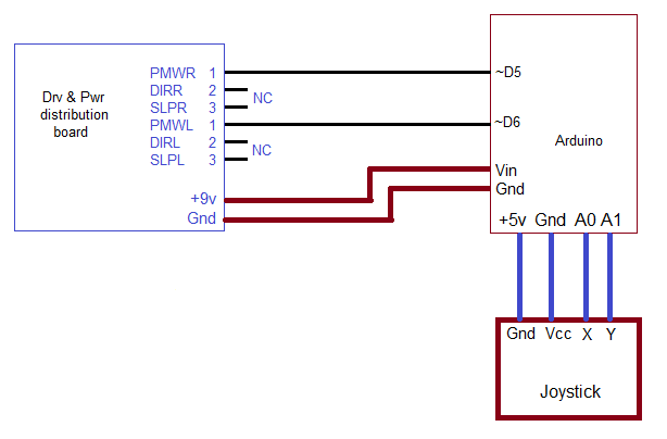
At this time I have the following:
DIR and /SLP: Not connected. At this time I am only interested in the motor speed control.
PWMR — A5
PWML —A6

The code:

Setup():

pinMode(5, OUTPUT); // Right motor
pinMode(6, OUTPUT);

Loop():

analogWrite (5,120); // Right motor
analogWrite (6,120);

To test different speeds, I vary the 120 constant. At this time, the motors spin at full speed as soon as I apply power and the value does not seem to matter.

I read the detailed information in the description page and noticed the truth table; however, I am not sure I am implementing this correctly. Is there an instruction or user guide that I can look at? Examples?

Thank you! SGarciav

Hi, SGarciav.

I am not familiar with the Adruino Go. Could you post a link to the product page for the Arduino board you are using?

-Claire

Thanks Claire!

I did not post a specific Arduino because I am using three: The Arduino Uno, Nano, and Pololu’s A Star 32U4. Regards, SGarciav

Pins 5 and 6 on those boards should be fine for outputting PWM signals and controlling the speed of the motors on the Romi. However, you mentioned connecting to pins A5 and A6 (which correspond to Arduino pins 23 and 4), which cannot output PWM. Could you post a diagram and pictures that show how you are connecting the power distribution board and Arduino?

-Claire

Thanks again.

My apologies for the confusing terminology. I am connecting the drv & pwr distribution board’s PWM inputs to the Arduino’s digital pins 5 and 6. Diagram follows.

Sgarciav

PS: I don’t have the circuit with me, so I can’t provide pics.

Addendum.,…

I took some pics. Here is a composite of the two showing the connector on the Pololu board, the header on the breadboard and the connections to the Arduino Nano (that I am using now). The connections on the Nano can’t be clearly seen because the wires going to D5 and D6 block them. The blue wire, corresponding to PWMR, goes to D5 and the black wire, corresponding to PWML, goes to D6. Regards, Sgarciav

From what I can see, those connections look okay, but it is not clear if you have a common ground connection. Could you try adding a connection from ground anywhere on the Romi board to a ground pin on the Arduino Nano?

If that does not help, could you post the full code you are using? If you use jumper wires to connect the DIR pins directly to 5V or ground can you get the motors to change direction?

-Claire

Thanks Claire, much appreciated!

I am going to say that I believe that the ground connection is ok because I am powering the Arduino from the 9v power supply that is integrated into the Romi chassis and goes through the driver & motor board. I am using the USB connection to the PC only to upload sketches to the Arduino. (That is another story.)

Since our initial exchange I have added a joystick to the setup to control the motors. The joystick is similar to this one:

https://postimg.org/image/8c9zqplj1/

Here is an updated connection diagram:

Oops, the diagram reversed the Vcc and Gnd connections to the joystick. Sorry about that. In real life, these are correctly connected.

And here is the complete sketch as I have it now


const int LMotor=6;
const int RMotor=5;
int val = 0;

void setup() {

  pinMode(A0, INPUT);  //
  pinMode(A1, INPUT);

  pinMode(LMotor, OUTPUT);  //
  pinMode(RMotor, OUTPUT);
  
  Serial.begin(9600);

}

void loop() {
 

   int leftStick = analogRead(A0);
   int rightStick = analogRead(A1);

   leftStick = map(leftStick, 0,1023, 0, 255);
   leftStick = constrain(leftStick, 0, 255);

   rightStick = map(rightStick, 0,1023, 0,255);
   rightStick = constrain(rightStick, 0,255);

   Serial.print("Left Stick: ");
   Serial.print(leftStick);
   Serial.print("         Right Stick: ");
   Serial.println(rightStick);

   analogWrite (LMotor,rightStick);
   analogWrite (RMotor,leftStick);
   
}

I will test the DIR signal and follow up with results.

Regards, SGarciav

Follow up:

I tested the DIR and /SLP lines.

The /SLP line works fine. Both motors stop when either /SLPR or /SLPL go to ground :-).

DIRR did not affect the motor direction, regardless of its state. The motor simply rotated forward.

DIRL, however, did correctly reverse the direction of the motor when Vcc was applied to it.

Again, thanks for your help, SGarciav

Thank you for posting and formatting your code. Adding a joystick at this point it just adding unnecessary complexity to the system, so can you take that out while we troubleshoot? Then, please post the full code you were using without the joystick.

It is a little odd to me that the DIR pin only worked for the left motor, and that makes me a little suspicious of a bad connection. Could you post pictures of the power distribution board that show your soldering? If you have a multimeter, you might also want to test your PWM and right DIR connections for continuity.

Did the power distribution board ever work properly for you?

-Claire

I was away and getting back now.

The power distribution board never worked. The DIR line seems suspicious; however, I am hoping that I am not using the right code to control the speed via the PWM pins. I connected the board this past week and only tested the DIR lines when I contacted you and you requested it.

I don’t believe the solder connections are the problem. I tested, and just retested by connecting Vcc directly to the DIR connector on the board, bypassing the solder points and cable that goes to the electronics board. As noted before. DIRL is ok, but DIRR is not reversing the motor.

Reposting code now:

const int LMotor=6;
const int RMotor=5;
int val = 0;

void setup() {


  pinMode(LMotor, OUTPUT);  //
  pinMode(RMotor, OUTPUT);
  
  Serial.begin(9600);

}

void loop() {

   analogWrite (LMotor,220);
   analogWrite (RMotor,150);

}

Thanks for your continued support! SGarciav

Thanks for posting the updated code. I do not see anything wrong with it. To confirm, did you have the same issue with the PWM not changing the speed with all three Arduinos? Could you try looking at the output of the PWM pins with an oscilloscope or multimeter to confirm they are actually PWMing? If you have not already, could you also try changing the PWM pins and connections to use pins 9 and 10 instead? If that does not work, it is possible that your board is damaged.

-Claire

And thanks for your continued help :slight_smile:

Ok, I will check the PWM pins to make sure that they are changing state and get back to you on that.

And yes, the PWM problem is present on all of the Arduinos.

I will also switch to pins 9 and 10 as requested and test - when I get home tonight.

To be continued …
Regards, Sgarciav

I tested :slight_smile:

First I standardized using the following code:


const int LMotor=5;
const int RMotor=6;
int val = 0;

void setup() {

  pinMode(LMotor, OUTPUT);  //
  pinMode(RMotor, OUTPUT);
  
  Serial.begin(9600);

}

void loop() {
 

   analogWrite (LMotor,1);
   analogWrite (RMotor,1);
   delay(1000);

   analogWrite (LMotor,250);
   analogWrite (RMotor,250);
   delay(1000);
}

This worked! I tested on the Arduinos that I have for development and it worked as expected. I also tested using pins 5/6 and 9/10 and both worked as expected.

The voltage on the pins varied from .1 v to about 4.7v.

The only issue that I can not resolve is the DIR pin not affecting the direction of the motor.

Thanks! Sgarciav

I am glad you got the PWM working. Since I have not seen pictures of it, my biggest suspicion for the DIR issue is still soldering or some other bad connection. Could you post pictures of the solder joints on the bottom of the board near the DIR connection?

-Claire

Thanks Claire,

I did not get the pic. Embarrassingly enough, I could not remove the motor controller board from the Romi chassis (sigh). I removed the two screws, but found that the battery contacts are affixed (soldered) directly onto the board. The flat contact (that goes to the positive end of the battery) can slide easily enough through the chassis, but the springy end that goes to the negative end of the battery gets caught because the hole on the chassis is too small for it to fit through.

Instead of forcing it through I want to ask you whether there is a more civilized process to remove the motor controller board. I can see that the solder points that you asked to see are somewhat visible through the chassis, without having to remove the board. If I can’t remove it, I will take the pic through the chassis and post it. Yo can let me know whether this is good enough or whether you want to see more of the board.

I will do this when I get home tonight. Thanks again! SGarciav

There is no other process for removing the spring battery contacts. It is a little tricky to push in the springs and get them through the holes, but once you get the hang of it, it is not too hard. I generally find it helpful to use a small screwdriver or other long flat object to compress the spring. If getting the whole board off gives you too much of a hard time though, you might be able to get a good enough picture of the solder joints by just pulling the board away from the chassis as much as you can.

-Claire

Claire, thank you for the tips! This made all the difference in being able to remove motor controller board. Such a simple solution that I did not think of!

Here is the picture that you requested: Regards, Sgarciav

The soldering looks okay in that picture, but I still recommend trying to retouch the DIRR joint just in case. If that does not help, it is possible that pin was damaged. If you email us at support@pololu.com with your order information and a reference to this thread, we can see what we can do to help you out.

-Claire

I retouched the DIR lines and there was no change. Looks like I’ll have to follow up with the Support email that you provided. Thanks much for your help, truly appreciated. Sgarciav