
I am using MMA7361L accelerometer(1.5g) in my snake-like robot to measure x and y axis velocity. Robot movement is completely on flat surface. I kept the accelerometer horizontal attaching with the body. When the system is still, accelerometer values are about 2.4 (almost half of Vcc=5). when the system is moving on flat surface, I got almost same values, no significant change at all. I can’t interpret the data. If acceleration data is okay then I can use band-pass filter and integrator (in MatLab/Simulink) to get velocity.
Please help me in this regard.
Hello.
We have two carrier boards for this accelerometer, one with a voltage regulator and one without. Which one are you using?
- Ben
I am using accelerometer board with voltage regulator.
Hello.
I am not sure why you are telling us the output is “almost half of Vcc=5V”. There is no Vcc pin on the board. You should make sure that a 5V supply is getting connected to the VIN regulator input; the output then has nothing to do with your supply voltage, and comparing it to Vcc is not meaningful. The regulated voltage is about 3.3V so with no acceleration, the outputs should be around 1.65V. 2.4V is about what you should expect on one of the axes if it’s turned the right way (because of gravity).
Can you post some pictures of your setup? It sounds like you might have the accelerometer buried in your robot, which is not great for troubleshooting. An easy way to test these is to connect power and an oscilloscope and then move the board around.
- Jan
Hi Jan,
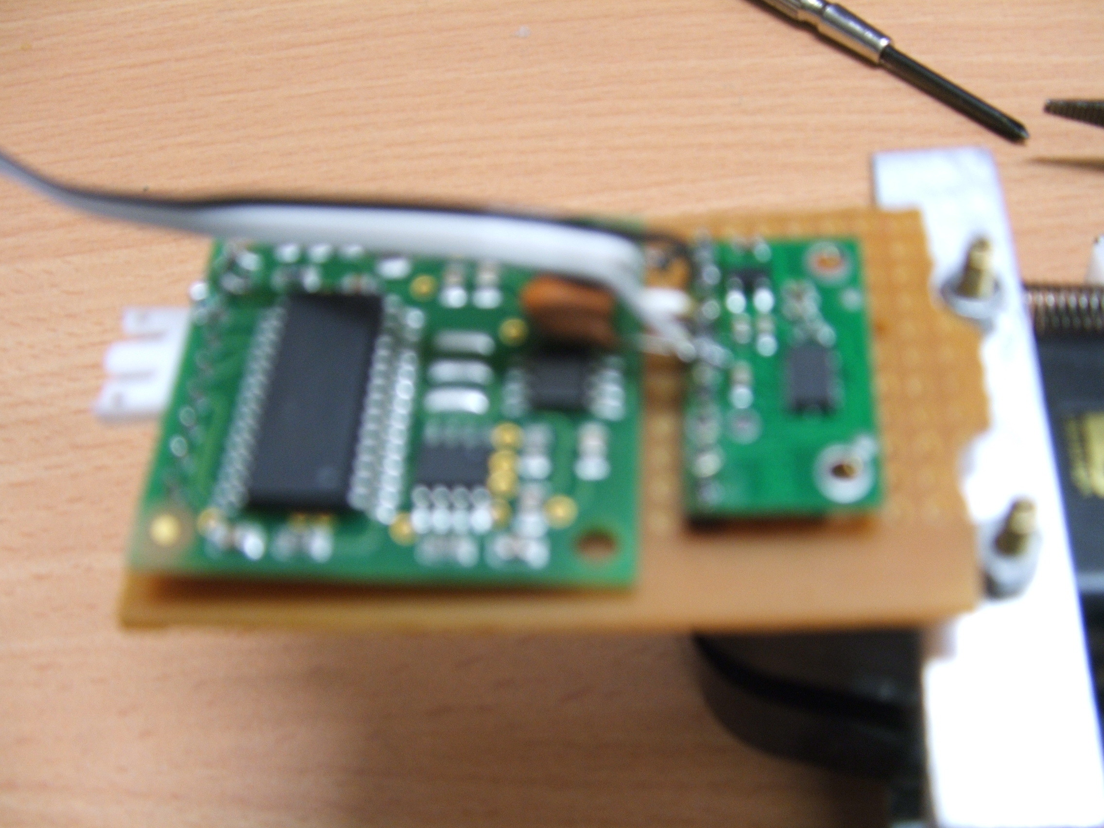
You are right. Their is no Vcc point, only has Vin point. Vin in my case is 5V. voltage regulator output is 3.2 volts. I attach the hardware figure here for you to have a look. It is very simply connected.
I am very much disappointed with the accelerometer data. Please guide me.
Regards,
Nurul
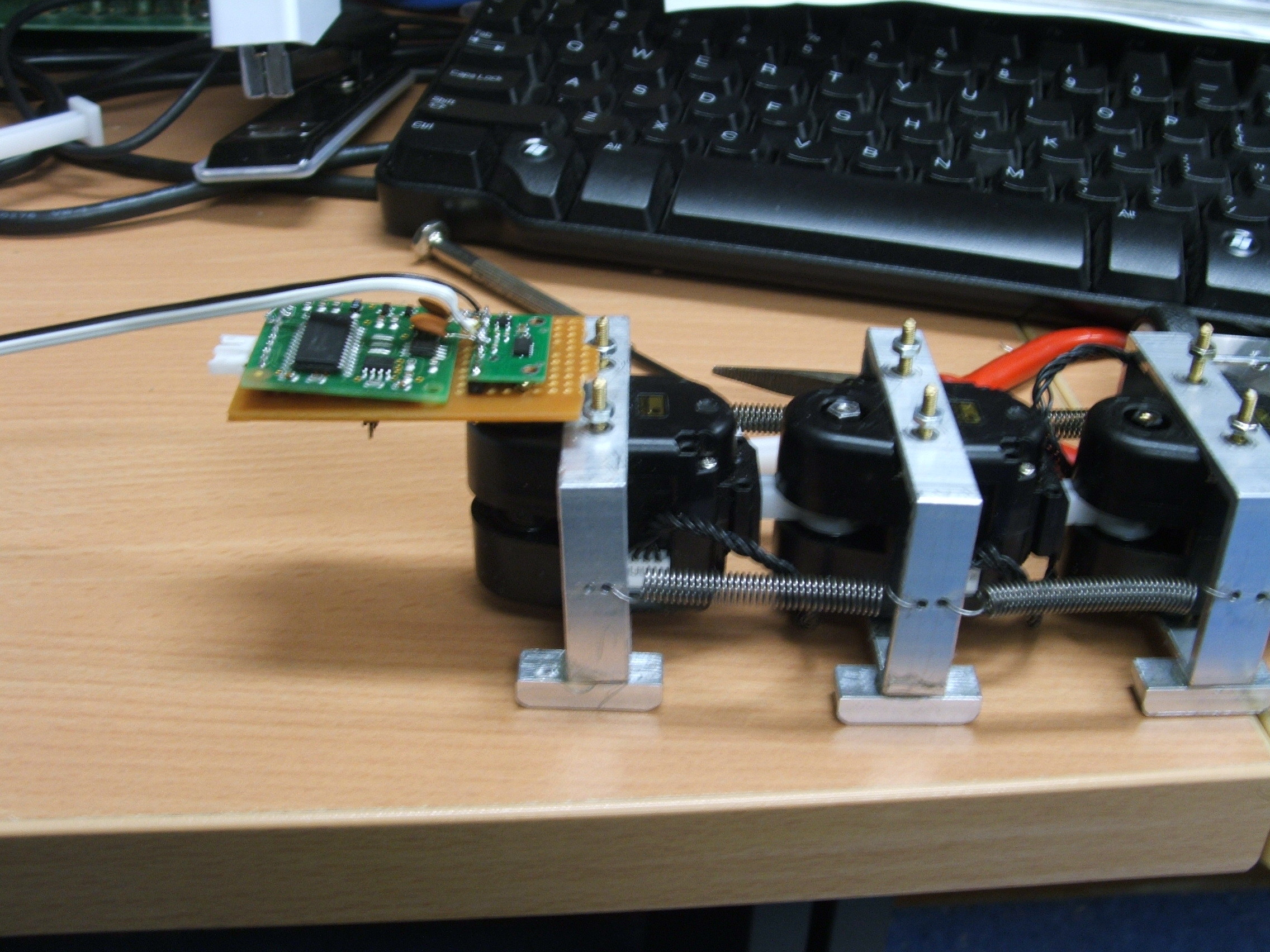
I post another figure, I am not sure why so poor resolution.
Compass sensor here is used for sensing angular movement, it is not related to accelerometer.
The second picture is a little better, but I still can’t really tell what you are doing from that. By the way, it looks like the pictures are out of focus, not limited by resolution. If you are going to post pictures, please make sure they are in focus and cropped appropriately.
Have you tried looking at the outputs on an oscilloscope without anything else (except power) connected?
- Jan
The second figure is better. I mount the PCB on robot module horizontally. On PCB two sensors I keep. Left on is compass sensor, right one is accelerometer. I tried to see the output on oscilloscope. It is also same 2.4V on both X and Y points either it is still or moving.
It’s strange for the outputs to both go to 2.4V since there is nothing special about that voltage as far as the sensor is concerned. In that picture, it looks like you have other things connected, so it’s difficult to trust that the voltage you’re seeing is not caused by whatever else is connected. Also, did you verify the voltage on the 3.3V node?
- Jan
Hi Jan, I have checked on 3V3 pin. it is 3.3V. So voltage regulator is alright I think. It’s connection is very simple. I also kept the accelerometer isolated from other with just 5V and Ground connection. Still it is same.
Well, I don’t have anything else to suggest. You can contact us directly if you want to try again, and we can give you a discount on a replacement.
- Jan
Hi, I bought a new one MMA7361l from an Australian Distributor. It’s now okay. But I can’t calibrate it rightly for velocity. I use it to measure x and y dimensional velocity of my moving snake on horizontal surface. It is moving forward (y-axis) around 7cm/sec.but i cannot read it. I get 2D acceleration data oscillating with bias 1.65V. I remove the bias and convert the volt to m/sec^2 dividing with sensitivity and multiplying with 9.8. Then I use bandpass/highpass filter to remove any offset before integration to get velocity. I found both axis velocity oscillating with average zero. but I have V_y(y-axis velocity) about 7cm/sec and v_x about 0. I do that on Simulink.
Please help me how to calibrate the accelerometer data for velocity.
Hello,
I do not think “calibration” is your problem. If you apply a high-pass filter to any set of data points and then integrate the data, you are going to get values fluctuating around zero. You probably will not be able to get anything much better than that using this kind of accelerometer.
I think that the best you can hope for is to start from rest and then measure your velocity for a few seconds until the errors build up to the point where your data is meaningless. Errors arise both from fundamental properties of the accelerometer like noise, drift, and nonlinearity (which you can read about in the datasheet) and from any tilting or turning. I imagine that a snake robot would do a lot of tilting and turning, giving you very noisy data.
Is a few seconds of velocity data going to be useful to you?
-Paul