Maestro Control Center
Channel 0 is set to output (audio trigger pin is connected to GND on channel 0)
Channel 1 is set to servo
Issue:
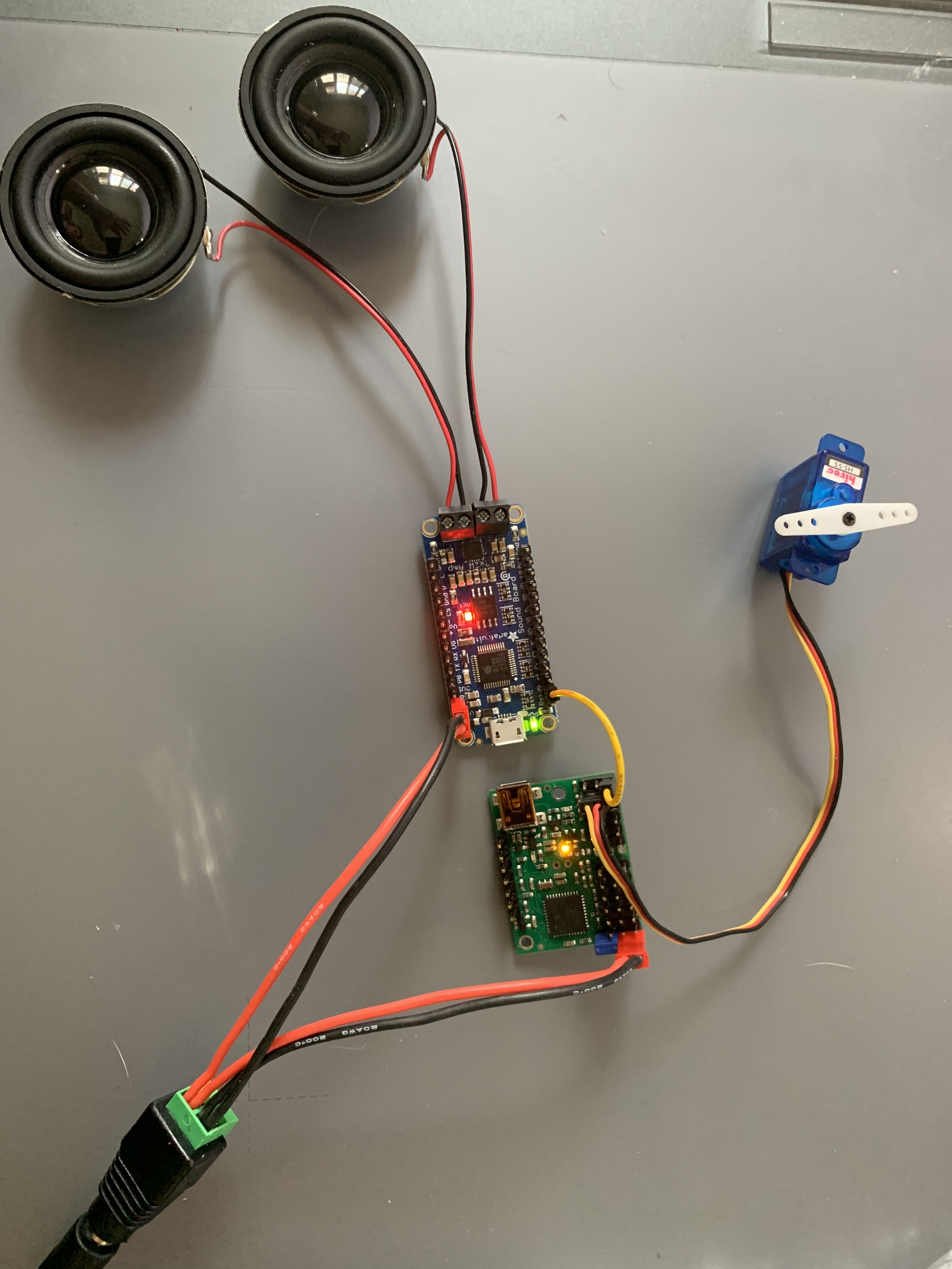
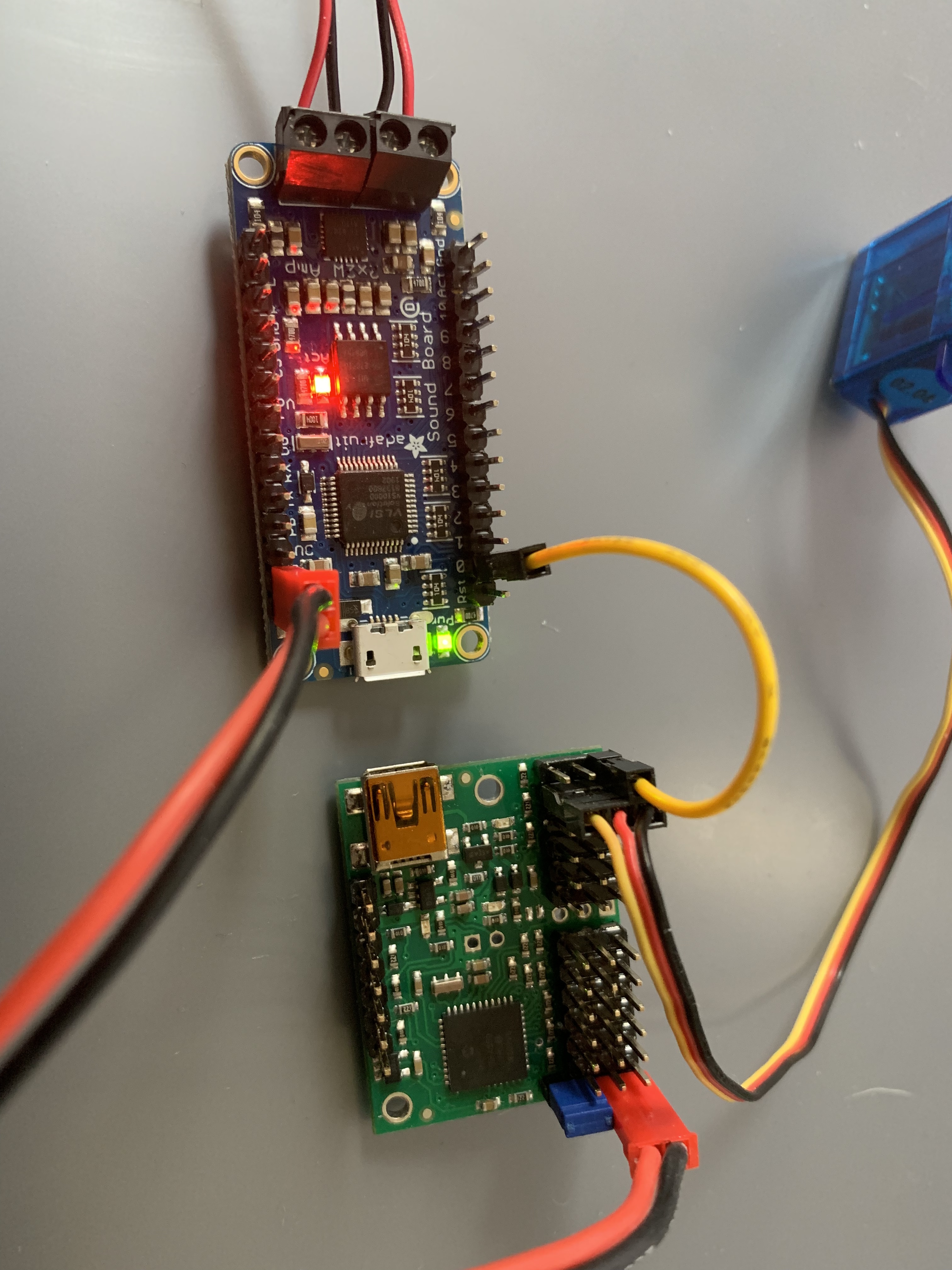
Everything seem to be connected correctly. Both boards are powered and I can control the server in the control center when hooked-up via USB. Unfortunately, I cannot seem to control the audio. The audio is supposed to trigger when the channel is grounded. Instead, the audio is just playing over and over as if it is being constantly triggered. I have tried any number of settings to see if I can control the signal from channel 0, with no luck. I believe it is set correctly (output) as I am not trying to trigger from a button press (input), and treating the channel as a servo seems to make no difference.
Am I misunderstanding how the Control Center works? Any insight to what I might be missing?
I changed the jumper on Channel 0 to the signal pin instead of GND (seems obvious in hindsight). I still wasn’t having success, but finally noticed that if the channel is set to Output in the Control Center and the position of the channel is at 1500, the sound doesn’t play. Drop one click below 1500 and it works.
As a noob, I can’t say I understand why this seems to be the solution, but I’m guessing that’s the point at which it is regulating the voltage to the pin. (I suppose what I mean to say is that the significance of the numbers 1500 vs. 1499.75 is lost on me as it relates to the actual voltage, but if that’s the switch that works, then whatever)
Would still appreciate some input just to make sure my configuration isn’t going to fry the components, but I’m encouraged that I might have gotten it figured out.
Your solution is correct; when a Maestro channel is set as an output, the position value of the channel is used to control whether the output is low (0 V) or high (VCC). Specifically, the output is low unless the position value is greater than or equal to 1500.00 μs. When we were writing the Maestro firmware we picked 1500 as the point where the digital output switches since it corresponds to a neutral position on a servo, but it could have been a different, arbitrary number. You can read more about it in the “Channel Settings” section of the Maestro’s user guide.