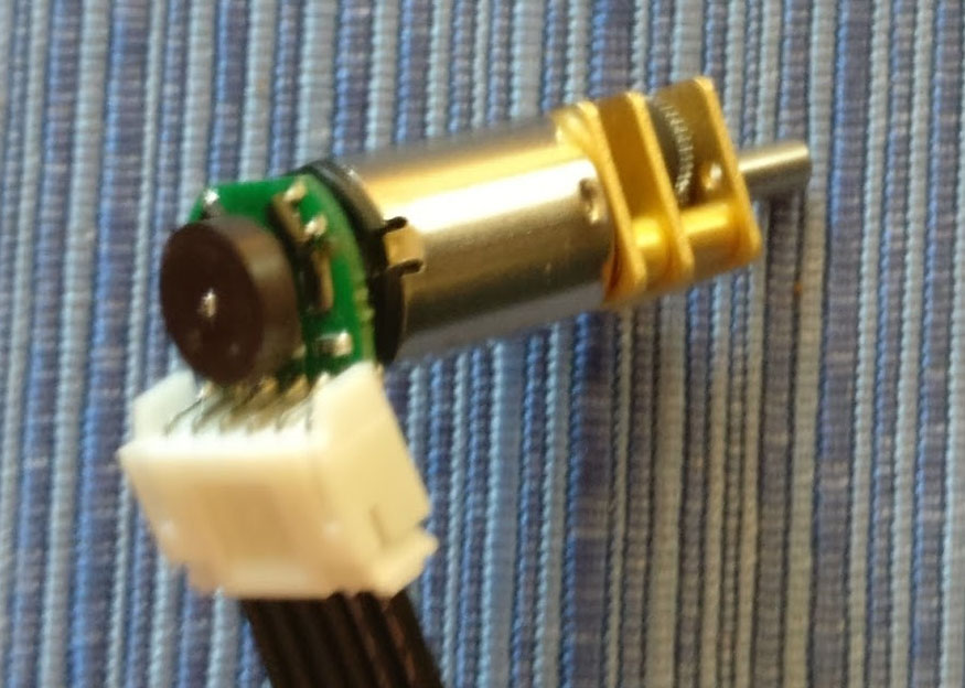
I have some Micro Metal LP gear motors with extended shaft, and the encoder/magnet kit to go with them.
Unfortunately, the terminals on the micro metal LP gear motor are so short, they only barely reach the underside of the encoder board (the motor has a boss around the extended shaft that limits how far down the board can go.)
I couldn’t find a good way to solder the board on there. In the end, I plugged the slots with solder, then heated it and dropped it onto the contacts, and made some kind of connection, but it’s only a little bit of unsupported solder keeping it on there.
Is this how it’s supposed to be? Are my terminals slightly short? Is the boss around the back shaft slightly high? Any advice on making a better connection than essentially dribbling solder on it?
These are supposed to work together.
However, the solder lugs on the back of the micro metal gearmotor just barely reaches the underside of the PCB; they don’t reach into the plated slot. I can kind-of make contact by pouring a solder slug through the slot and to the lugs, but that doesn’t seem mechanically sound…
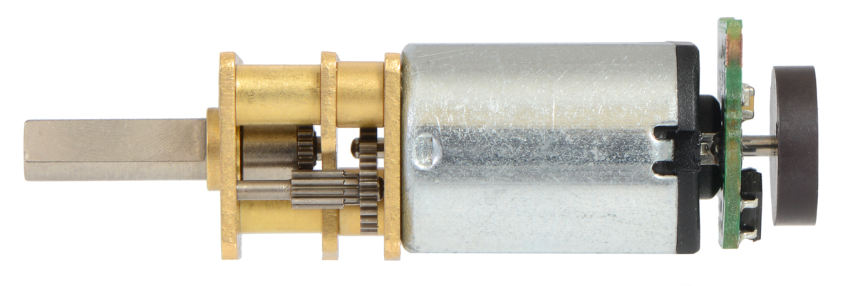
This picture from your site shows the lugs, and seems to indicate that the lugs should reach all the way into the slots, but it’s kind-of hard to tell for sure:
I can’t quite get a good picture from my install, because it’s deep in a robot, and evenso, the lugs are now covered in said solder blob. Imagine if the solder lugs just reached the end of the black boss in the middle of the motor back, so they kind-of touched the plane of the encoder PCB, but didn’t reach into the plated slot; that’s what I’m seeing.
Those motor terminals should extend about 0.6mm beyond the output shaft bump on the back of those motors, which should let them extend about halfway into the holes in the PCB. If you just fill the holes with solder with the board resting flat against the bottom of the motor, that should be sufficient to make good electrical connections while securing the board mechanically.
You can see the expected dimensions in the gearmotor dimension diagram. Are your gearmotors not consistent with this?
Ah, I had not drawn the correlation there. Thanks for the link! According to the data sheet, the bump is 50 thou and the lugs are 70 thou, so about 508 microns of lug stick-out (presumably with less precision than that particular number would indicate.)
Is it within spitting distance of 0.5mm ? Quite likely. The data sheet doesn’t have variance in dimension called out, so it’s hard to tell what’s “in spec” or not, but I’d expect so. Thanks for clarifying!
Btw, the JST PH series of connectors is a common 2mm pitch connector that actually fit pretty well on the board. I got the angled contact, which angles away from the magnet and sticks out the side, and then cut off the bottom pins on the underside after soldering so they don’t hit the metal casing of the motor.