Maestro mini 12 - powering servos from different sources

Hello,

I have a 2 groups of servos, 3 of them require 7.2V while other 3 need 6V. I need a way to power them up with appropriate voltage and still use Maestro power controller (which unfortunatly has only one power rail).

I was thinking, is it possible to wire Maestros PWM signals from signal pins to other board? On the other board ill have sockets for servos and ill power them with what they need while the PWM signals will be wired from Maestro board.

Is it possible? If yes, are there are any dangers of doing so? Do i need to wire it in some specific way? Maybe use two twiseted wires for PWM signal (where other one will be GND) or something. Maybe i need to still connect the servo VSR power (GND) pin?

What would be most recommended wiring for that?

Hello.

You can power the servos separately from the Maestro board (either directly or through some other power rail as you mentioned). If you do this, you would need to make sure that the servo power still shares a common ground with the Maestro board.

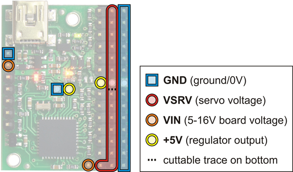
Alternatively, there is a trace on the bottom of the board that can be cut to separate the power rail into two, allowing for different voltages to be used on each. The cuttable trace is indicated by the dashed line in this picture:

-Brandon

1 Like

thank you

Hi Brandon,

Thanks for the tip. I am looking to do the same thing. I have 9g servos on channels 0 and 1 and MG995 servos on channels 6 and 7. I can’t seem to find a happy medium to supply power to both at the same time. Either the 9g servos jitter or the MG995 servos are slow or non-responsive.

Can you be more specific about cutting the trace? How would I supply the two separate voltages after splitting the rail? Which rail would still have power after splitting and which would I have to introduce a 2nd source to?

Thanks,

IntStarFoo

Hello.

Cutting that trace separates channels 6-11 and channels 0-5 into two separate power banks. Supplying servo power across the + and - pins on any channel in a given bank (or the VSRV pin in the case of the channel 6-11 bank) would provide the same supply for all of the channels in that bank. For example, supplying 6V to channel 1 after cutting that trace would provide 6V to channels 0-5 when connecting to that bank’s power and ground rails.

By the way, that behavior sounds like your power supply might not be able to provide enough current for all four of your servos when they are straining at the same time.

-Jon

Also, remember to connect all grounds together, power source ground, maestro ground and servos ground because the PWM signal has to have a common point of reference.