Hey guys,
I have a little problem with the reset behaviour of the LV-DSMC.
Hardware Setup:
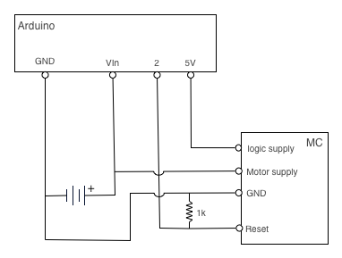
I use the LV DSMC to drive the Arduino RoverKit. The MC is connected to Serial1 of an Arduino Mega, the MCs reset (with 4k7 pull-down) is connected to PWM2. The motors are shielded with 3 capacitors (0.1µF) each. The whole system is powered by a 1000mAh 7.4V LiPO.
Problem Description:
If the reset line is set to LOW, the MC does not always stop the motors. Most of the time, the motors will continue moving in the last direction but with maximum speed.
Software:
/* Pololu LV DSMC DEBUG */
#define LED_PIN 13
#define MOTOR_RESET_PIN 2
#define MOTOR_SPEED 0x42
unsigned char motorCommandBuffer[6];


void setup()
{
  pinMode(LED_PIN,OUTPUT);
  pinMode(MOTOR_RESET_PIN,OUTPUT);
  Serial1.begin(9600);
  resetMotor();
}

void loop()
{
  motorForward();
  delay(2000);
//  reset_motor();
  deactivateMotor();
  digitalWrite(LED_PIN,LOW);

  delay(2000);
  digitalWrite(LED_PIN,HIGH);
  resetMotor();
}

void deactivateMotor()
{
  digitalWrite(MOTOR_RESET_PIN,LOW);
  digitalWrite(LED_PIN,LOW);
}

void activateMotor()
{
  digitalWrite(MOTOR_RESET_PIN,HIGH);
  digitalWrite(LED_PIN,HIGH);
}

void resetMotor()
{
  deactivateMotor();
  delay(150);
  activateMotor();
  delay(150);
}

void motorForward()
{
  //left motor
  motorCommandBuffer[0]=0x80;              //start byte - do not change
  motorCommandBuffer[1]=0x00;              //Device type byte ? do not change
  motorCommandBuffer[2]=0x01;              //Motor number and direction byte; motor one =00,01
  motorCommandBuffer[3]=MOTOR_SPEED;       //Motor speed "0 to 128" in hex  (ex 100 is 64 in hex)
  for(int i=0; i<4; i++)
    {Serial1.print(motorCommandBuffer[i], BYTE);}

  //right motor
  motorCommandBuffer[0]=0x80;
  motorCommandBuffer[1]=0x00;
  motorCommandBuffer[2]=0x03;      //Motor number and direction byte; motor two=02,03
  motorCommandBuffer[3]=MOTOR_SPEED;
  for(int i=0; i<4; i++)
    {Serial1.print(motorCommandBuffer[i], BYTE);}
}
It’s definitely strange for your motors to be running when the controller is reset. Here are a few possible issues:
Your power supply is beyond the maximum of 7.0V.
The reset line has a 4.7k pull-up, so your 4.7k pull-down is not a particularly good value. Something like 1k would be better since that would actually pull the line close to 0 when you don’t drive it yet let you override it with your I/O line.
Your LED is not actually on the reset line, so it’s not the best indicator of its status. Why don’t you put the LED on the reset line? Better yet, can you look at it with an oscilloscope?
If that doesn’t help you fix the problem, please provide more information about your logic power setup.
I have imagined that you would say that.
For the following test I have replaced the 7.4V LiPo by 4*AA. It has not changed the strange behaviour by any means.
Ok, the pull-down now has 1k. Unfortunately this has not fixed the problem.
The LED was not intended to be used as a direct trace for the reset line but as a generic indicator. So I only have changed the software to mirror the state of the reset line.
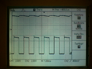
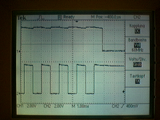
Here are some oscilloscope snapshots:
Channel 1 is the reset line and Channel 2 is M0. Both channels are set to 2.0V per square. The time base is 1ms.
You can view the full trace (about 1 min) at:
I have used the 5V output of the Arduino board to supply the MCs logic.
We were not able to reproduce your results here, so there’s probably a problem with your particular unit. Does the problem happen with both motors and in both directions?
I just looked at your video again, and I see that the LEDs are behaving as expected, and they are before the H-bridge, so it’s possible that something like a static discharge or the supply overvoltage changed the input characteristics of the chip we’re using as the MOSFET driver.
One thing that might help, if you have the parts and tools for it, is putting in smaller pull-down resistors on the PIC outputs. You should see four 100k resistors between the 8-pin PIC and the 28-pin part above it (they’re marked “104”). Putting in something like 10k might help (if you have them, you can just solder them in parallel on top of the existing 100k parts).