
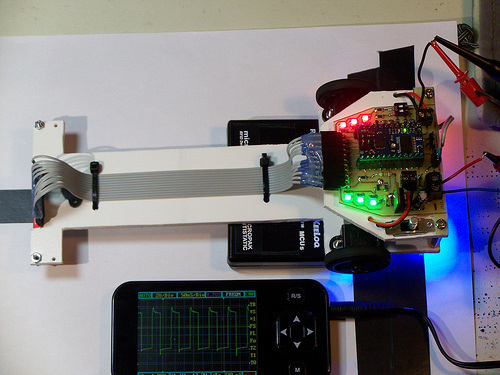
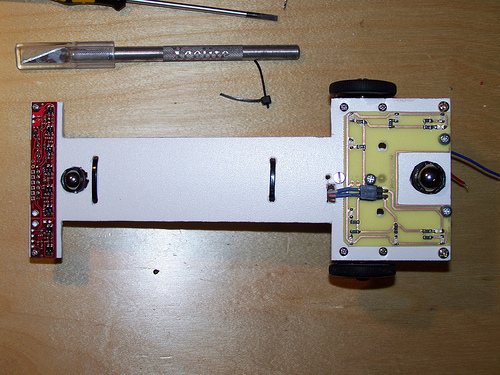
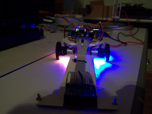
Hello, my line follower robot with Baby Orangutan, QTR-8A (reading in digital) and 10:1 micro metal gearmotor.
video:

All the necessary steps to build the robot: jmnlab.com/robotzero/robotzerov.html (spanish)
Hello, my line follower robot with Baby Orangutan, QTR-8A (reading in digital) and 10:1 micro metal gearmotor.
video:
All the necessary steps to build the robot: jmnlab.com/robotzero/robotzerov.html (spanish)
Very nice!
Did you etch the board yourself? What kind of transfer process did you use.
Also, somewhat unrelated, how do you like the DSO Nano oscilloscope?
-Adam
Hello, thanks. I use the ultaviolet light method and ferric chloride. The DSO nano is like a cheap multimeter, it is not very accurate but if you don’t own a real oscilloscope, it can be usefull. It only allow you to measure very slow speed signals. Here you can see pictures of a review, with different frequency signals: jmnlab.com/dsonano/dsonano.html
Hello.
Thanks for sharing, including that review (we have been thinking about selling that product). I’m just working off of the automated translation, so sorry if you covered this, but overall, would you recommend it? Have you used any PC-based oscilloscopes, and if so, how does the DSO Nano compare?
- Jan
Hello, I have never used a pc-based oscilloscope.
I didn’t buy the DSO nano (I won it at a website contest) and don’t recommend it… It is cheap but the bandwidth is very low and only has one channel. If you want to work with microcontrollers a saleae logic is the best choice.
Hello, the final version of my line follower robot:
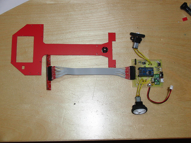
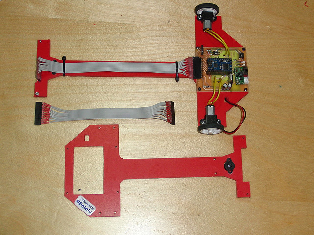
2 x Pololu 10:1 Micro metal gearmotor HP.
Baby Orangutan B-328.
QTR-8A Reflectance sensor array.
Pololu wheel 32x7 mm.
Pololu ball caster with 3/8" metal ball.
Pololu micro metal gearmotor bracket pair.
Pololu adjustable boost regulator 2.5-9.5 V.
3.7 V Lipo battery.
PD control.

Average speed: 2.1 m/s (minimum bend radius: 30 cm)
The code, schematics, pcb (spanish): webdelcire.com/wordpress/archives/350
I think if you make your robot a little shorter, it will turn curves more efficiently. It is going out of line sometimes because it is so long.
What do you mean by “more efficiently”? If the rules let you do it, the farther out your sensors are, the more time you have to react to the upcoming curves.
- Jan
Hi, the idea is to have several robot bases with different lenghts and widths in which to assemble motors, electronics and sensors, in this way you can adapt the robot to different circuits.
To find the optimal length and width of the robot is not an easy thing, you have to take into account the robot reaction time, inertias, frictional forces, etc…
I did evrithing like they seed on the robot zero page and when i try to set the Kd is not working…i mean the Kp is ok ,my robot is foolowing the line with some balance but when i try to set the kd it is no differene between kd=1 and kd=1000…i hope you can help me …i dont really know much about the pid algotithm…