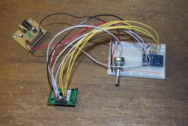
I bought a couple of the small LCD displays (Pololu item 356 - pololu.com/catalog/product/356) but I’m not sure how to connect them to a microcontroller. I couldn’t find the pin usage in the documentation referenced by the example programs, but the header file seems to make that clear. I’m trying to run this from a Baby-Orangutan first, here’s a picture of my setup
It’s kind of hard to see, but I’ve got things connected like this
When I run the lcd3-hello-world sample program I just get square boxes along the top row which go away after a couple seconds. Every now and then the boxes show up again for a couple seconds.
Is this the right pinout? I’ve got the contrast adjusted so the boxes are just barely visible before running the program.
Eventually I want to hook them up to an atmega 328p on a board I’m working on, so I should also ask if these same pins will work on a bare 328p (I’ll be using the Pololu library).
It looks like you’re making connections based on the code for the Orangutan SVP, which uses a different microcontroller (ATmega324/1284) from the Baby Orangutan (ATmega48/328). When you run the Pololu AVR library’s LCD routines on your Baby Orangutan, they are trying to control the LCD with different pins. You should try connecting your LCD in a way that matches the schematic for the Orangutan SV-328, minus the user buttons and green LED. This means that in addition to correcting your I/O pin connections, you should also ground the unused LCD pins and add a pull-down on the R/W pin.
These same pins should work on a bare ATmega328 running the Pololu AVR library as long as that AVR is running at 20 MHz. If the clock speed is different, the delay functions will behave differently, and the LCD initialization timing will be off. You can fix this by rewriting the library’s delay functions so that they’re accurate at your MCU’s clock speed, or you can edit the LCD library to make the delays in the initialization routine longer (or it might just work if the clock speed is close to 20 MHz).