I’ll try using 470uF @ 100v. I don’t have an oscilloscope to see if there are any voltage spikes or anything so we’ll just have to see if they fry or not. Thanks for your help.
There is something i did not really understand.
I have also followed this doc
explaining why as low as possible ESR is better for bypass capacitors and you also say in your tuto that “extremely low ESRs are generally a benefit”
but you add :
“but do very little to dampen LC oscillations”
so there seems to be two phenomena that need to be reduced :
LC oscillations requiring large ESR
something else * requiring low ESR
The article above clarifys a little bit this something else
The first line of defense against unwanted perturbations on the
power supply is the bypass capacitor. A bypass capacitor
eliminates voltage droops on the power supply by storing
electric charge to be released when a voltage spike occurs. It
also provides this service at a wide range of frequencies by
creating a low-impedance path to ground for the power supply.
It’s not so clear for me what distinguises the two phenomena and why they require completely opposite (conflicting) properties of the capacitors (Low vs High ESR)
ESR limits the current in and out of the capacitor. Low ESR allows the capacitor to give a lot of current to the local circuit if it needs it, which is generally good. (The “something else” “pheonomenon” in your second bullet point is your circuit not working because it did not get the power it needs.) However, low ESR means that the capacitor can also draw a lot of current when you initially apply some voltage to it, and when you do that with long wires, that’s where you add inductance to the system and get the oscillation problems. You don’t “require” large ESR to deal with that; there are several other things you can do. It’s just that low ESR does exacerbate the problem, and if you don’t need it that low, adding some back can be the easiest way to balance keeping the oscillations good enough while also keeping the power to your circuit good enough.
and use it to feed an arduino from a Lipo 4S (16.8 V max) in a quadcopter.
At the end of your page there is the recommandation:
“If you are connecting more than 20 V or your power leads or supply has high inductance, we recommend soldering a 33 μF or larger electrolytic capacitor close to the regulator between VIN and GND. The capacitor should be rated for at least 50 V.”
Though my Voltage is lower than 20V, i’m still wondering if with ~ 15cm leads (typical breadboard wires) it would be more cautious to add the electrolytic capacitor in parallel with the polulu regulator … ?
For your system, you probably do not need to add an electrolytic capacitor, but adding one would not hurt either, so if you have space for it, you might add it just as a precaution.
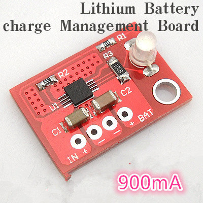
I have a Pololu 6V 2.5A step down regulator D24V25F6. VIN connects to 12V solar panel and OUT is connected to a CN3065 lithium battery charge module using a 2.3 metre cable.
In my project, I am finding that the CN3065 boards are experiencing problems after a few weeks of use. Normally the CN3065 would stop charging the lithium battery once the voltage reaches 4.2v. But after a while the boards are supplying higher voltage (approx 5v) to the battery. This is a problem as these batteries should not be charged higher than 4.2v.
The datasheet for the CN3065 states that the maximum input voltage is 6V which the Pololu regulator is providing, so I am wondering if voltage spikes on powerup could be damaging the CN3065. There is a mechanical switch near the lithuim charge module to switch power on/off.
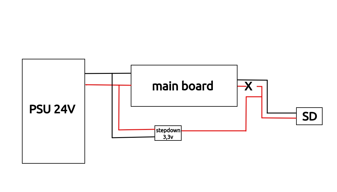
I have a 3D printer Creality Ender3 and i want to use a SD card Flashair W-04 (SD+Wifi) with microSD to SD adpater. the main board not have sufficient power for feed the SD card for power up the Wifi module. then i want use a 3,3v(500mA is sufficient) stepdown between the main board and the SD card with cut the 3,3v power from the main board and inject the power from the external stepdown
Using the regulator you mentioned with a 24V power supply and no electrolytic capacitor could have caused an LC spike that damaged the regulator, so if you had your system configured like that and it is not working, you might try to replace the regulator and use an electrolytic capacitor this time. By the way, if you have access to a benchtop power supply with an adjustable voltage, you could try powering the Flashair module you mentioned with 3.3V from that to see if it works. Also, you might try powering the regulator with a 12V supply and testing the output to see if it provides 3.3V with no load.
I have recently fried two 3.3V regulators (S9V11F3S5C3), quite literally (the main chip on the bottom of the board molten). Could the voltage spikes be that destructive?
My setup is 12V (battery-backed PV system), long lines (10-15 meter), then the regulator and a 3v3 logic board (which uses 300mA max, but usually 30mA or less). Occasionally the system is switched on and off near the battery with a switch.
I’m reasonably sure my voltage never goes above the 16V maximum rating, so the voltage spike article seems like a good lead, but adding the electrolytic capacitors is going to be challenging space-wise so I thought I’d check here first.
A setup like that does sound prone to experiencing significant spikes. It is possible that an LC spike could have been the initial cause of damage, then continuing to try to operate the regulator after it was already damaged could have led to even more destruction.
However, it is hard to know what is really going on without actually observing it, so you should look at the voltages in your setup with an oscilloscope to be more certain.
Thanks! Looking at the signal with an oscilloscope is going to be challenging (this being a PV setup, there isn’t any 220V outlet anywhere near to plug in an oscilloscope, and of course on the workbench at home everything works just fine), so I guess 'll just add a suitably big capacitor and try.
Frankly, your tests with the power supply make no sense or at least the explanation makes no sense.
When constant voltage is suddenly applied to a series LC circuit, voltage spike on C is never a function of L, it’s always at most twice the voltage applied, and is usually less due to resistance of the wires, ESR, etc. This is just the basic math of an LC circuit, and can easily be verified in LT Spice.
I think in your first set of tests the power supply itself was overshooting somehow trying to regulate the output, and that’s why you saw those 40V spikes.
Last set of tests with the battery is much more in line with the theory because it’s just the battery, rather than an actively regulating power supply device.
There is an inductance of the wires of course that’s contributing to the voltage swing on the capacitor, but that inductance alone cannot explain the 40V spike. The power supply is doing something funky.
We just tried it again and confirmed you can get a spike over 2x the supply voltage even with a battery. (We had to help this particular battery out with an electrolytic capacitor across it to help it quickly supply the necessary current.)
I suspect the main thing you probably did not capture in your simulation if you did one is the voltage dependence of capacitance, which is especially bad in ceramic caps. With an otherwise identical setup, we get bigger spikes with lower-voltage rated caps. And the length of the leads definitely made a difference, too.